Building a 3D-Printed Beamsplitter Camera Rig
A practical, adjustable Stereo3D rig for two Blackmagic Micro Studio Camera 4K G2 bodies
beamsplitter rig, stereoscopic camera, Stereo3D, Blackmagic Micro Studio Camera 4K G2, FreeCAD, 3D printing
Project overview
Why use a beamsplitter rig?
A side-by-side camera rig cannot place two camera bodies closer together than their physical width. That becomes a serious limitation for interviews, tabletop scenes, and other close subjects, where a smaller interaxial distance is required for comfortable Stereo3D.
This rig places two Blackmagic Micro Studio Camera 4K G2 bodies at roughly 90 degrees around an optical beamsplitter. One camera photographs through the glass and the other photographs its reflection. Their virtual optical centres can therefore be brought much closer together than the camera bodies themselves. The mirror box is 3D printed, while standard 15 mm rods, clamps, and Arca-style plates provide the adjustment.
The build was designed as a practical and affordable system: matched power-zoom lenses, BRAW recording from each camera to its own 1 TB NVMe SSD, an iPad for stereo monitoring, and Blackmagic’s camera-control API for synchronized lens control.
Construction video
The first video shows the physical components and the assembly of the prototype.
Watch the construction video on YouTube
This is a prototype carrying two cameras and a front-surface optical mirror. Inspect every print, clamp, and fastener before use, add safety tethers, and support the complete rig from a properly rated tripod. Handle the mirror only by its edges and follow the supplier’s cleaning instructions.
Optical and mechanical design
How the beamsplitter optical path works
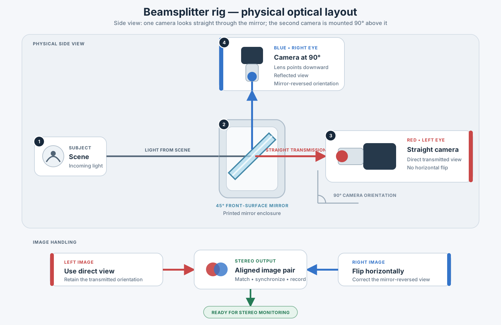
The reflected camera view is laterally reversed, so it must be flipped before the two eyes are compared or edited. A good stereo monitor makes this obvious: show both inputs as anaglyph or difference, apply the flip, and use a grid to remove vertical error before judging horizontal disparity.
The beamsplitter also introduces optical compromises. Reflection and transmission are not perfectly identical, and dust or fingerprints are visible in one or both paths. Match exposure and white balance with a chart, shade the mirror box from stray light, and clean the optical surface carefully.
The printable mirror box
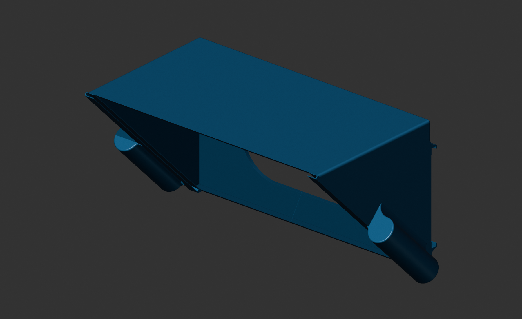
The supplied FreeCAD model contains the mirror holder, shade support, lens opening, and inside/outside rod-holder geometry. Its approximate overall envelope is 251 × 128 × 149 mm, so check the usable build volume of the printer before slicing.
Two versions are provided:
- Download the editable FreeCAD model — use this to inspect the parametric construction or adapt dimensions.
- Download the printable STL — import this into the slicer for fabrication.
FreeCAD is a free, open-source parametric CAD application. New users can begin with the official Basic Part Design tutorial and the Part Design Workbench documentation.
The CAD geometry suggests a mirror near 210 × 160 mm, but this is an engineering estimate—not a cutting specification. Measure the final printed slot, check the insertion direction and edge clearance, and confirm the chosen glass thickness before placing the mirror order.
Printing recommendations
The time-lapse below shows the beamsplitter enclosure taking shape on the printer. The long walls form the shaded optical chamber, while the angled central geometry supports and protects the mirror.
- Open the STL in the slicer and inspect all mirror-seat and rod-holder surfaces.
- Orient the part for strong layers around the 15 mm rod supports rather than simply minimizing support material.
- Use sufficient perimeters and infill for a camera-supporting prototype. Material, nozzle, and print orientation matter more than a universal infill percentage.
- Print a short test section of the mirror slot and rod interface first.
- Deburr carefully. The coated mirror must never be forced against a rough printed edge.
Components and budget
Parts list
Prices below are a working estimate checked on 29 July 2026 and are shown consistently in US dollars. Korean prices are converted at the same indicative rate of US$1 = ₩1,477.41: ₩24,440 for each capture cable, ₩349,300 for each BC711 SSD, ₩47,500 for each UX980 enclosure, ₩28,050 for the Y201 clamp, and ₩19,400 for the macro rail. Marketplace prices vary by country, seller, login state, variant, VAT, and promotions. Where a current public price could not be verified, the table says so and excludes it from the subtotal.
| Qty. | Part | Image | Purpose and purchase link | Unit price | Subtotal |
|---|---|---|---|---|---|
| 2 | Blackmagic Micro Studio Camera 4K G2 |  |
Required matched left- and right-eye cameras, treated as existing equipment; Blackmagic product page | About $995.00 | Not included |
| 2 | Panasonic Lumix G X Vario PZ 14–42 mm lenses | 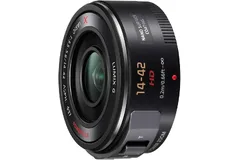 |
Matched Micro Four Thirds power-zoom lenses; Amazon listing and Panasonic specifications | $148.00 | $296.00 |
| 1 | Apple iPad | 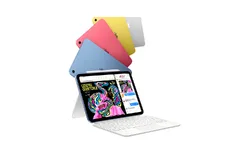 |
Stereo monitor and control interface for anaglyph comparison, grid, image flip, and alignment; Apple iPad | From $449.00 | $449.00 |
| 2 | Coms HDMI-to-USB-A/USB-C capture cable, 1.8 m | 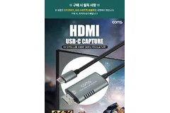 |
Brings both independent HDMI outputs into the iPad; Coupang product 7235376771 | $16.54 | $33.08 |
| 1 | Cable Matters USB-C 4-port Gigabit Ethernet switch | 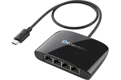 |
Creates the wired camera-control network; USB-C powered with four Gigabit RJ45 ports; Amazon ASIN B083ZMKXZQ | $31.99 | $31.99 |
| 2 | SK hynix BC711 1 TB M.2 NVMe SSD | 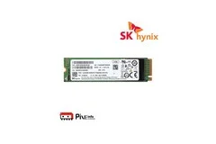 |
One dedicated BRAW recording drive for each camera; Coupang product 6305565211 | $236.43 | $472.85 |
| 2 | Reviewan UX980 NVMe M.2 USB enclosure | 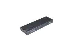 |
Houses each BC711 SSD and connects it as an external recording drive; Coupang product 1458570836 | $32.15 | $64.30 |
| 1 | Optical beamsplitter mirror |  |
Front-surface/tint-free mirror from Stereoscopic Mirror; estimate uses 210 × 160 mm, 2 mm glass | $60.04 | $60.04 |
| 1 | CAMVATE/HDRIG C3646 L-shaped cheese plate | 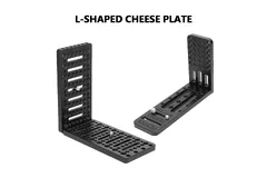 |
Structural camera-mounting plate; AliExpress item 1005007463243464 | $31.80 comparable retail | $31.80 |
| 1–2 | BEXIN QJ-06 double-lock Arca clamp | 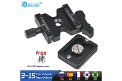 |
Quick-release adjustment for the camera support; AliExpress item 1005005048413420 | $11.13 | $11.13–22.26 |
| 1 pair | NICEYRIG 15 mm rods, 30 cm | 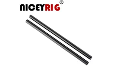 |
Main support rails; AliExpress item 1005003394153510 | $12.99 | $12.99 |
| 1 | 90-degree 15 mm rod clamp | 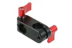 |
Joins perpendicular rail sections; AliExpress item 32887249075 | $3.59 | $3.59 |
| 1 | MAGICRIG Y201 single-hole 15 mm rail clamp | 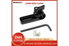 |
Additional rod fixing; AliExpress item 4001220541356 | $18.99 | $18.99 |
| 1 | Macro focusing rail / Arca slide | 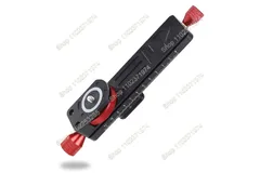 |
Fine fore–aft camera positioning; AliExpress item 1005008877672634 | $13.13 | $13.13 |
| 1 | Printed mirror box | 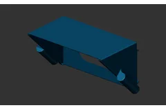 |
Fabricate from the downloadable STL; includes the mirror seat and rod-holder geometry | Filament-dependent | — |
Price summary
- Rig hardware, mirror, and monitoring interfaces: approximately $450–$550
- Complete rig package, excluding the cameras: approximately $1,400–$1,700
For practical planning, budget about $500 for the rig components if the cameras, lenses, iPad, and recording drives are already available. A complete rig package with the lenses, iPad monitoring, recording drives, network switch, mirror, and mounting hardware is roughly $1,500, excluding the cameras.
Two Blackmagic Micro Studio Camera 4K G2 bodies are required to operate the rig, but they are treated as existing production cameras and are not included in the rig price. At the US$995 reference price, purchasing both cameras separately would add approximately $2,000.
The rig-package range allows for ordinary price changes between sellers, variants, and exchange rates. Filament, small fasteners, cables, a USB hub, tripod support, shipping, VAT, and import duties can move the final cost beyond this range.
This article documents a working prototype, not a fixed commercial kit. The final build may require additional clamps, cables, adapters, fasteners, printed spacers, power accessories, or replacement components. Part availability, product revisions, dimensions, prices, and the exact mounting arrangement can also change.
Before ordering, verify every component against the current CAD model, camera connections, mirror dimensions, iPad configuration, and intended tripod. Allow extra time and budget for testing, revisions, and small parts discovered during assembly.
The supplied AliExpress order-history link names the same BEXIN QJ-06 clamp already listed above. A public product URL is used here because a private order page is not a reliable link for readers.
Technical system schema and architecture
Technical system schema
The schema is the central reference for assembling and troubleshooting the electronic system. It shows the two camera chains, their independent recording media, the shared monitoring interface, the wired control network, and the V-mount power distribution in one view.
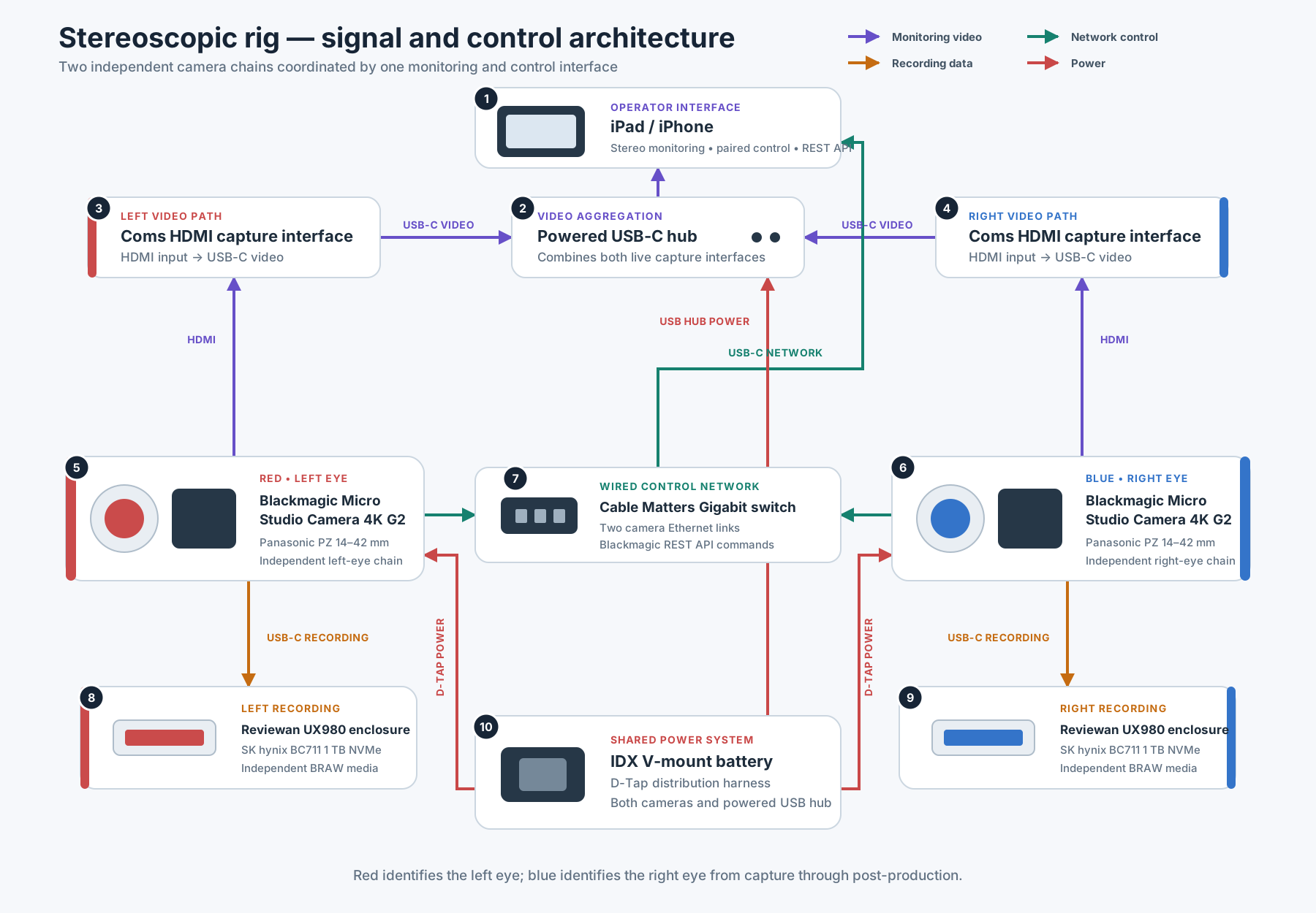
Numbered component legend
The legend belongs to the schema above: every number maps directly to one diagram block and its connections.
| No. | Component | Function in the rig | Connections shown in the schema |
|---|---|---|---|
| 1 | iPad or iPhone | Operator interface for dual-view monitoring and synchronized camera control. | Receives both USB video feeds from 2. Sends control traffic through 7 to cameras 5 and 6. |
| 2 | Powered USB-C hub | Aggregates the two capture interfaces and wired network connection for the mobile device. | Video from 3–4 and network from 7 join here; the host link continues to 1. Power comes from 10. |
| 3 | Left HDMI capture interface | Converts the left camera’s HDMI output into USB video. | Camera 5 → capture 3 → hub 2. |
| 4 | Right HDMI capture interface | Converts the right camera’s HDMI output into USB video. | Camera 6 → capture 4 → hub 2. |
| 5 | Left-eye Blackmagic camera and lens | Captures the red-coded left image. | HDMI to 3; Ethernet to 7; BRAW to 8; power from 10. |
| 6 | Right-eye Blackmagic camera and lens | Captures the blue-coded right image. | HDMI to 4; Ethernet to 7; BRAW to 9; power from 10. |
| 7 | Cable Matters Gigabit Ethernet switch | Distributes camera-control commands. | Links device 1 with cameras 5–6. |
| 8 | Left recording drive | Stores left-eye BRAW media. | Dedicated USB-C recording connection from camera 5. |
| 9 | Right recording drive | Stores right-eye BRAW media. | Dedicated USB-C recording connection from camera 6. |
| 10 | IDX V-mount battery and D-Tap distribution | Powers both camera chains and the monitoring hub. | Separate branches feed cameras 5–6 and hub 2. |
Line colors: purple = monitoring, green = camera control, orange = recording, and red = power. Eye colors: red = left, blue = right.
The architecture deliberately separates four functions. Live pictures, camera-control commands, recorded media, and electrical power follow different paths so that one interface does not have to carry the complete production load.
Physical component layout
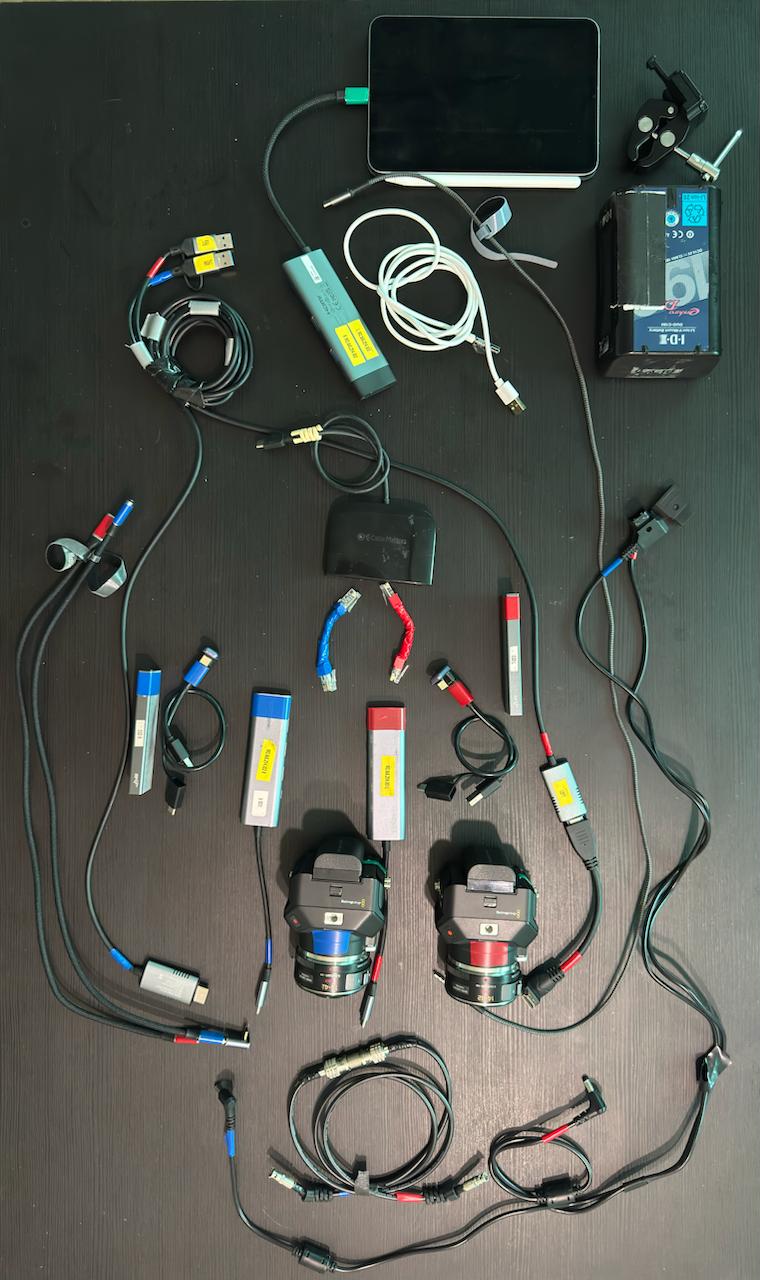
The photograph below shows the electronic system laid out before installation on the mechanical rig. Red and blue tape provide a consistent visual code: red identifies the left-eye path and blue identifies the right-eye path. This is especially useful when identical camera, recording, network, and power cables are routed close together.
Additional physical hardware
- Battery mounting plate and support clamp — the mechanical assembly beside the V-mount battery.
- D-Tap splitter and DC adapter leads — the physical harness represented by power block 10.
- Short USB-C and adapter cables — connect the numbered monitoring, recording, network, and power blocks.
Monitoring video path
The purple path carries live pictures for framing and stereo evaluation. The left camera 5 sends HDMI to capture interface 3, while the right camera 6 sends HDMI to capture interface 4. Both interfaces convert HDMI into USB video and enter the powered hub 2, which presents the two feeds to the iPad or iPhone 1.
This monitoring path is used for anaglyph comparison, image flipping, grids, and disparity checks. It does not carry the high-quality BRAW recordings.
Camera-control network
The green path carries Blackmagic REST API commands. The iPad or iPhone 1 communicates through the wired network and Gigabit switch 7, which provides separate Ethernet links to the left and right cameras 5–6. The software can therefore send paired lens, exposure, codec, frame-rate, and audio settings without mixing command traffic with the HDMI monitoring feeds.
Recording paths
The orange paths are deliberately independent. Left camera 5 records its BRAW media directly to drive 8, and right camera 6 records directly to drive 9. The live-monitoring device does not sit between the cameras and their recording media, reducing bandwidth conflicts and preserving two separate camera originals for post-production.
Power distribution
The red paths originate at the IDX V-mount battery and D-Tap distribution system 10. Separate branches power the two cameras 5–6, while another branch powers the USB-C hub 2 used by the monitoring interfaces. Keeping camera and accessory feeds on defined branches makes the system easier to inspect, isolate, and troubleshoot in the field.
Before operating the rig, verify the voltage, connector polarity, current capacity, and fuse protection of every branch. Signal-cable colors and left/right eye colors are identification aids; they do not indicate electrical compatibility.
Cabling and remaining build requirements
The two cameras and iPad are now included in the priced parts list. The system still requires:
- a powered USB-C hub if the selected iPad cannot accept both Coms capture cables and the Ethernet interface directly
- short, high-quality USB cables connecting each UX980 enclosure to its camera
- two short Gigabit Ethernet patch cables for the camera-control network
- camera power, video, and control cables
- a suitably rated tripod, baseplate, and safety tethers
- matched fasteners, washers, and any printed spacers required by the final build
Building the physical rig
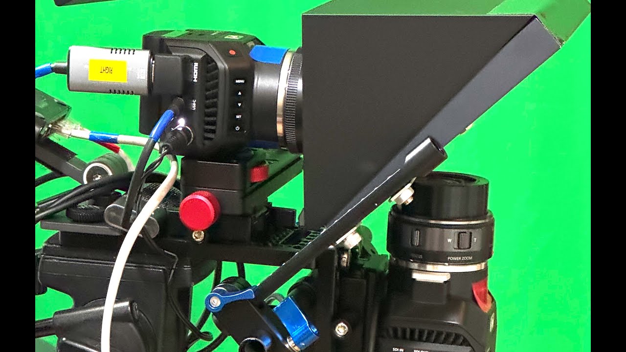
Mechanical assembly sequence
- Print and inspect the mirror box. Test the 15 mm interfaces and mirror slot before installing any optical glass.
- Build the rail frame. Fix the main rods to the cheese plate and add the perpendicular clamp arrangement. Keep every joint accessible for adjustment.
- Mount the direct-view camera. Place its lens centrally behind the transmitted optical path without touching the printed shade or mirror holder.
- Mount the reflected-view camera. Position it at approximately 90 degrees to the first camera and centre its lens on the reflected optical path.
- Install the beamsplitter. Confirm the coated-surface orientation with the mirror supplier, protect the edges, and secure it without bending or point loading the glass.
- Balance the complete assembly. The tripod connection should sit close to the combined centre of mass, with all clamps clear of the controls and cables.
Monitoring, networking, and camera control
The monitoring and control system uses separate paths for live images and camera commands. HDMI-to-USB interfaces carry the two eye views, while the wired Ethernet network carries Blackmagic REST API control.
Dual-camera monitoring on the iPad
Each camera’s HDMI output is connected to its own Coms HDMI capture cable. The two USB video signals enter the iPad—through a suitable powered USB-C hub when required—and the monitoring application displays both eyes together. This is the working alignment instrument for the rig, providing dual-camera input, anaglyph comparison, a grid, horizontal offset, and the flip required for the mirror-reflected view.
The product advertises support for a 4K60 HDMI input. Confirm the actual USB capture format and frame rate inside the monitoring application; an input rating does not necessarily mean that the USB output is delivered at the same resolution.
Wired camera-control network
The two cameras share a compact wired network through the Cable Matters USB-C 4-port Gigabit Ethernet switch. It is powered over USB-C, avoiding another mains-powered switch on the rig, and provides four Gigabit Ethernet ports. Connect one camera to each RJ45 port with a short Ethernet patch cable. The remaining ports can serve the control device or an uplink when required.
The USB-C connection can act as both the switch’s power source and a Gigabit Ethernet adapter for a compatible host. If the iPad’s USB-C connection is already occupied by the capture interfaces, integrate the switch through the powered USB-C hub or power it separately from a stable USB source. This network carries camera settings and synchronized lens-control commands through Blackmagic’s REST API; high-bandwidth monitoring continues over the two HDMI capture paths.
Control software for iPad and iPhone
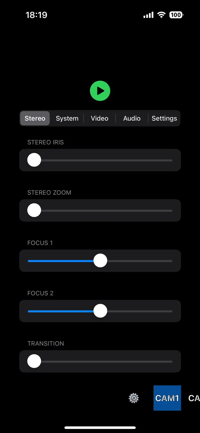
The custom control software turns an iPad or iPhone into a single interface for the two Blackmagic cameras. Instead of changing identical settings separately on each body, the operator can configure the pair, make synchronized lens and exposure adjustments, and switch between the left and right cameras from one screen.
The software uses the wired Ethernet network for Blackmagic REST API commands. On the iPad, the two HDMI capture interfaces provide the live left- and right-eye images used for stereo evaluation. The phone interface offers the same compact control structure when a smaller control surface is preferable.
Control data travels over Ethernet through the Cable Matters switch. Monitoring video travels over the two HDMI-to-USB capture interfaces. This keeps camera control independent from the live video feeds.
Stereo lens controls
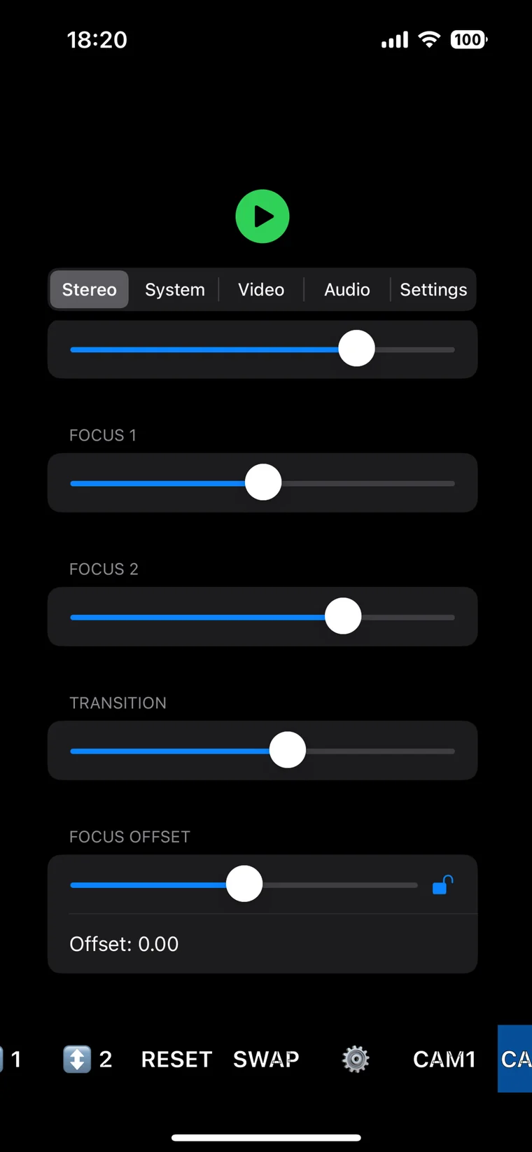
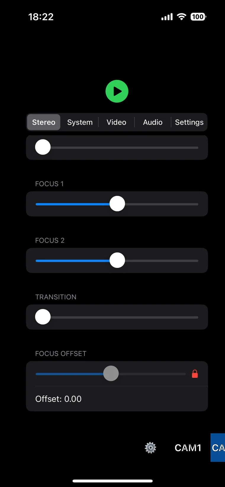
The Stereo panel is designed around the adjustments that must be coordinated on a dual-camera rig:
- Stereo iris changes exposure on the matched pair together.
- Stereo zoom moves both power-zoom lenses as a pair.
- Focus 1 and Focus 2 retain independent focus control for calibration.
- Transition adjusts how quickly a commanded lens move is applied, allowing smoother synchronized changes.
- Focus offset preserves a deliberate difference between the two lenses. The offset can be locked to prevent accidental changes.
- Reset restores the paired control state, while Swap exchanges the left/right camera assignment.
- CAM1/CAM2 selection allows inspection or adjustment of an individual camera without losing the paired workflow.
Matched video and exposure settings
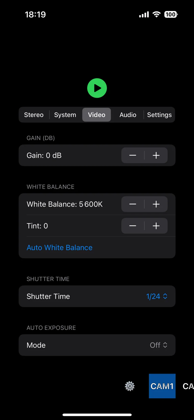
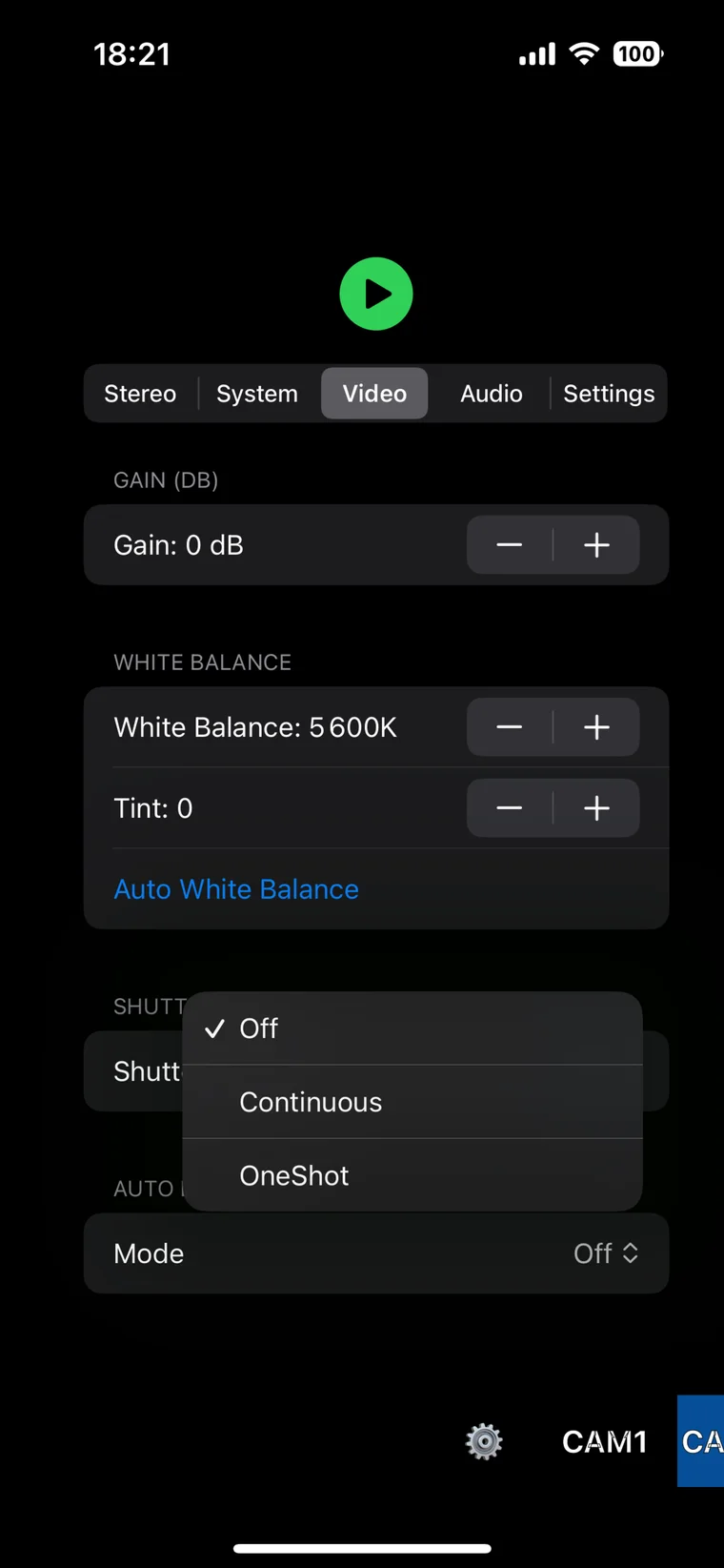
The Video panel applies core shooting parameters from a shared interface:
- gain in decibels
- white balance and tint
- automatic white balance
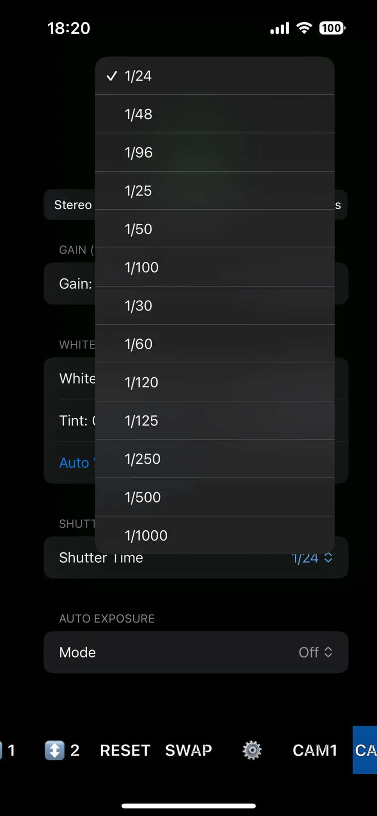
- shutter time
- automatic exposure modes: Off, Continuous, and OneShot
The shutter menu includes common cinema and broadcast values from 1/24 through 1/1000 second. Because stereo depends on temporal and photometric consistency, both cameras should normally use the same gain, white balance, shutter, and exposure mode.
Recording format and frame rate
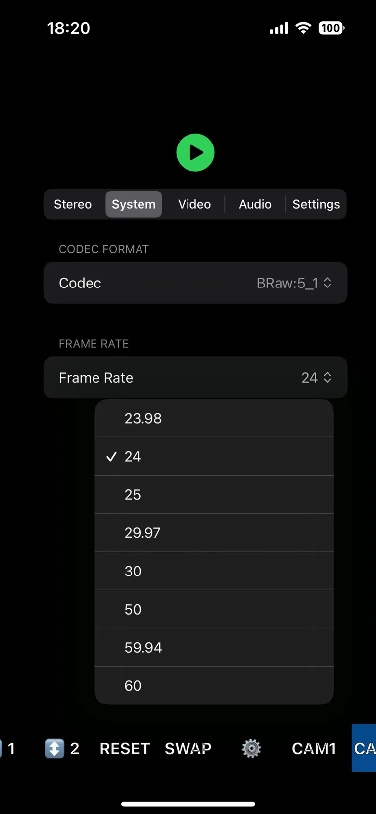
The System panel configures the recording codec and frame rate. The example shows Blackmagic RAW 5:1 and offers 23.98, 24, 25, 29.97, 30, 50, 59.94, and 60 fps. Applying these parameters through the shared interface reduces the risk of recording a stereo pair with mismatched formats or time bases.
Two-channel audio control
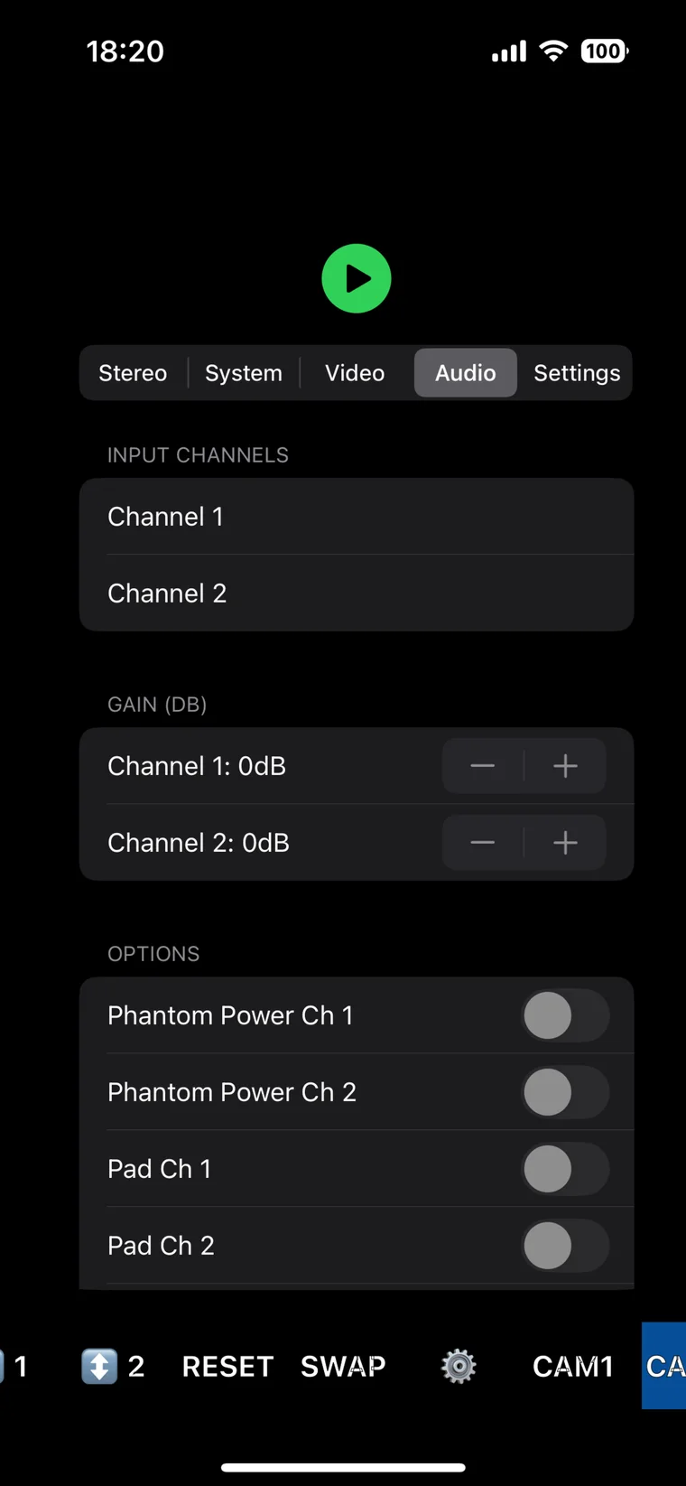
The Audio panel exposes both input channels, individual gain controls, phantom power, and input pads. Audio settings can therefore be checked without leaving the paired-camera control environment.
Camera addressing
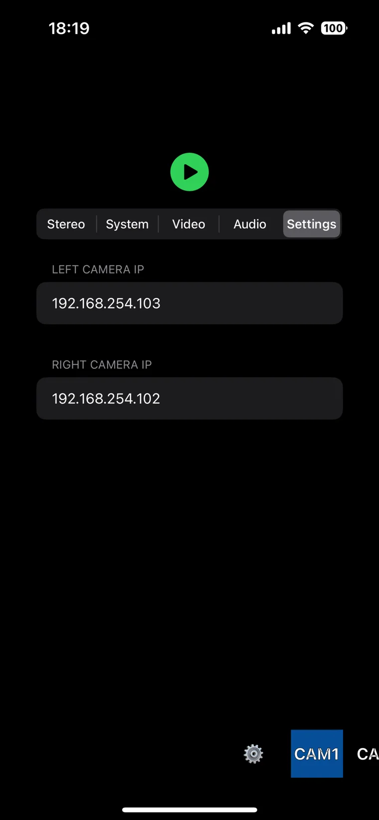
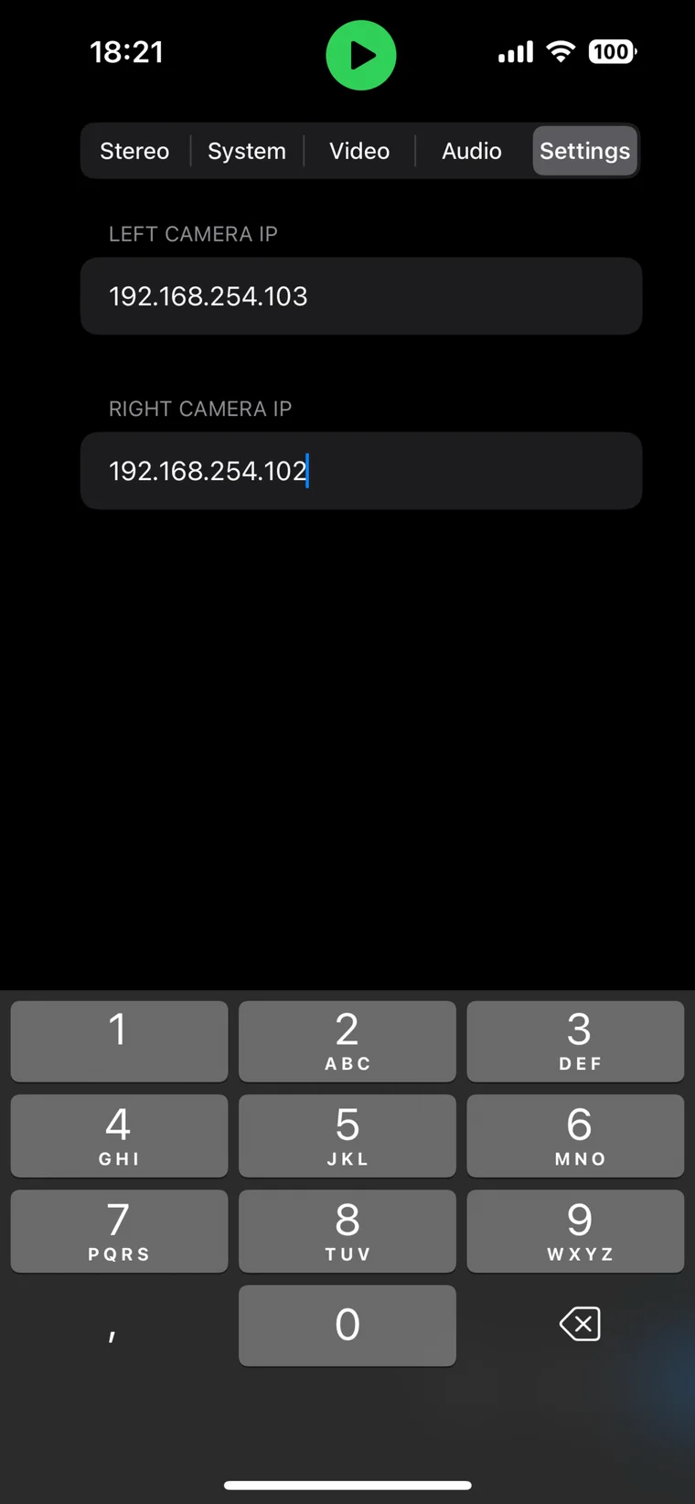
The Settings panel stores separate IP addresses for the left and right cameras. This is the connection between the software and the physical camera assignment on the Gigabit Ethernet switch. The addresses remain editable when the network configuration changes.
Alignment and calibration
Perform alignment in a controlled order. Changing an early mechanical setting after disparity adjustment forces the later steps to be repeated.
Calibration workflow
- Match resolution, frame rate, shutter, ISO, white balance, codec, and lens focal length.
- Square both cameras mechanically and centre each lens on its optical path.
- Flip the reflected view in the monitor.
- Correct roll and vertical disparity using a distant grid or calibration chart.
- Adjust the virtual interaxial distance for the subject distance and intended screen.
- Set horizontal composition/convergence deliberately; never use convergence to hide vertical misalignment.
- Record a chart through both optical paths and compensate any exposure or colour difference caused by the mirror.
- Confirm recording synchronization. A brief flashlight event provides a simple visual sync reference when reviewing both files.
Matched power-zoom lenses are especially helpful because zoom changes can be sent to both cameras together. The prototype also uses Blackmagic’s REST API for synchronized lens control and records each eye as BRAW on its own SSD.
Field test: the rig in operation
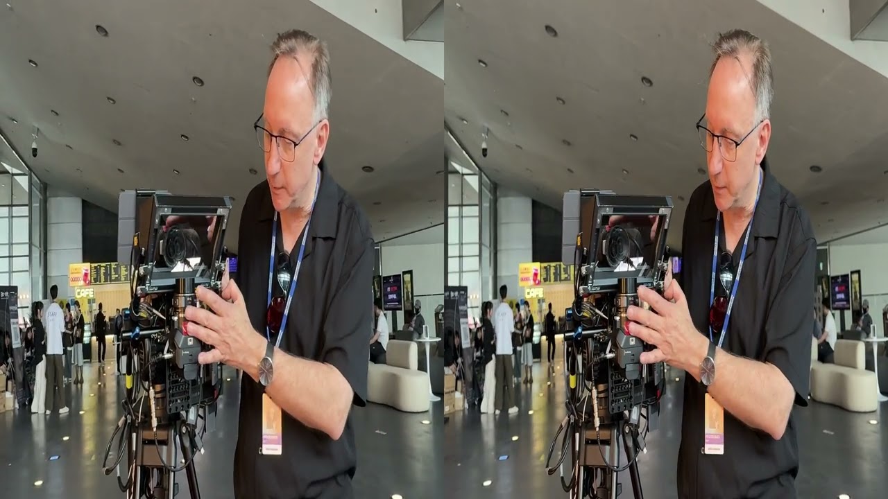
The second video gives a working overview recorded during the Busan International Short Film Festival, after a 3D workshop. Test material from the system was screened in a cinema in 3D and 4K.
Watch the working-rig overview on YouTube
Practical limitations and future revisions
The strength of this design is that the specialized part—the mirror box—can be printed and modified in FreeCAD, while the adjustment system uses common cinema-rig components. The exact clamp count and plate arrangement can change with the tripod, camera accessories, and balance requirements.
Treat the CAD, videos, and parts list as a documented starting point. Measure the mirror seat, verify every marketplace listing, test the optical alignment, and adapt the hardware to the way the rig will actually be used.