Stereoscopic Photography and Stereobase Calculation
A friendly guide to choosing the distance between two cameras
stereobase, stereoscopic photography, interaxial distance, parallax, stereo comfort, thin lens
Why stereobase matters
Hold one finger in front of your face and look at it first with your left eye, then with your right. The finger appears to jump sideways against the background. Your brain uses this small difference between the two views to understand depth.
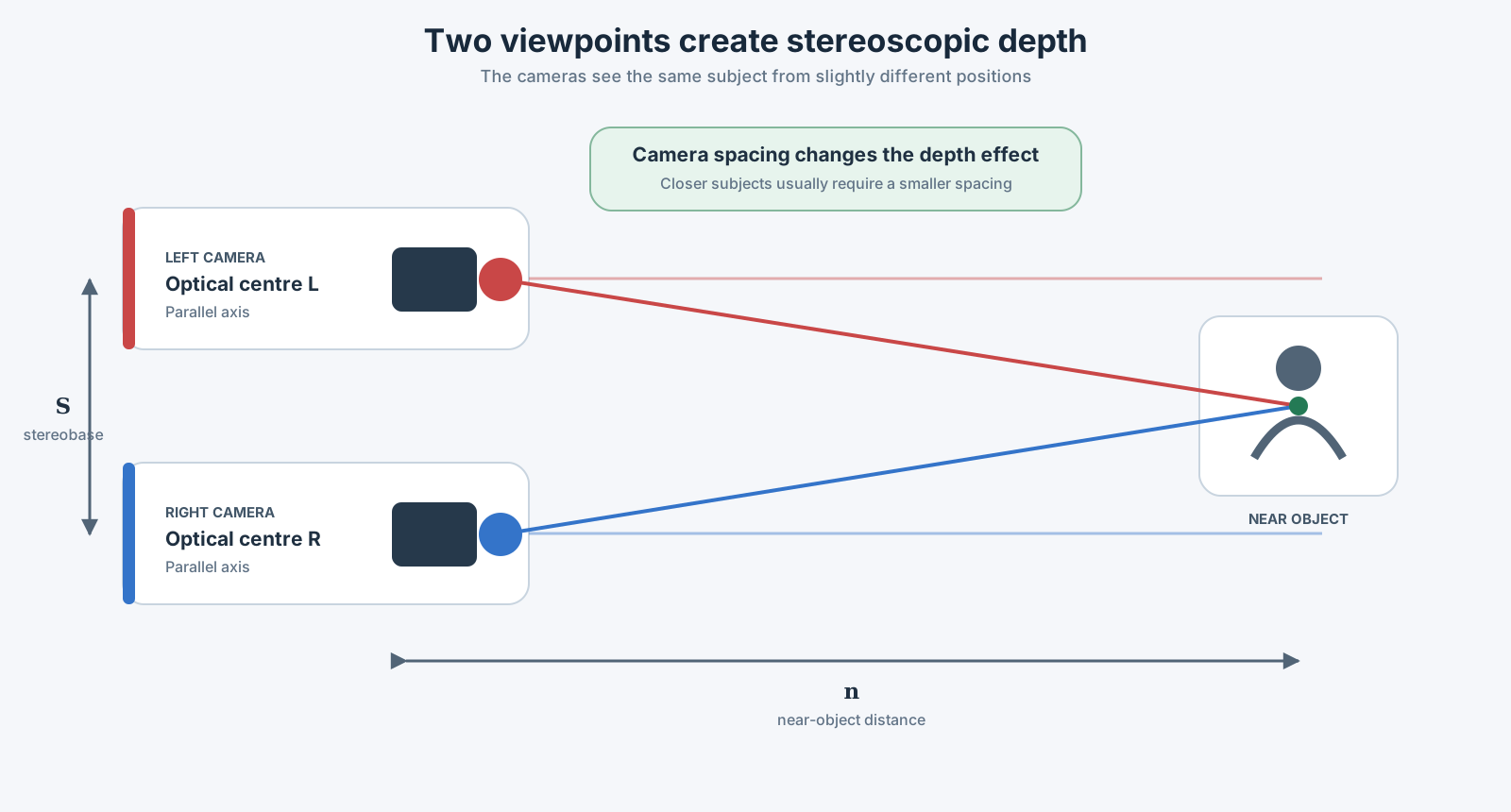
A stereoscopic camera works in the same way. It records one image for the left eye and another for the right eye. The distance between those two camera positions is called the stereobase.
Think of the stereobase as the depth control of the camera rig. Moving the cameras farther apart makes the two pictures more different. Moving them closer together makes the pictures more similar.
This changes how the finished 3D image feels:
- Too little difference: the image may look almost flat.
- A useful difference: depth is clear and comfortable.
- Too much difference: the eyes struggle to combine the two pictures.
A spacing that works for a distant landscape may be far too wide for a person standing close to the cameras. The final screen also matters: a tiny difference in the recorded images becomes much larger when projected across a cinema.
A wider camera spacing usually creates stronger depth. A smaller spacing usually creates gentler depth. If the spacing is too large for the subject and the final screen, viewing can become tiring or uncomfortable.
This page teaches one simple calculation so you can see how the main choices are connected. Real productions contain more variables, but you do not need to learn all of them before understanding the basic idea. Calculate a starting value, test it with the real cameras, and adjust it while watching a proper stereo display.
The three knobs that change the result
Most of the calculation can be understood through three practical choices:
How close is the nearest important subject?
A person three metres away needs more care than a mountain three kilometres away. Closer subjects usually require the cameras to be closer together.Which lens are you using?
A wide lens and a telephoto lens place the scene on the sensor differently. The focal length therefore changes the result.How large will the image be shown?
A phone, television, headset, and cinema screen enlarge the recorded left–right difference by very different amounts.
The calculation asks a practical question:
How far apart can the cameras be while keeping the left–right image difference within the limit chosen for the final screen?
Why the final screen changes everything
A tiny camera difference can become large
Imagine printing a small photograph as a cinema poster. Every feature becomes larger. The same thing happens to the difference between the left- and right-eye images when they are projected on a large screen.
On the camera sensor, that difference may be less than one millimetre. On a cinema screen, it may grow to several centimetres.
First, find the enlargement
If a sensor width of \(w\) is enlarged to a screen width of \(W\), the enlargement factor is
\[ M = \frac{W}{w}. \]
In plain language, this means:
enlargement = screen width ÷ recorded image width
This is only a scale comparison. If the screen is 200 times wider than the recorded image, every measured separation in that image also becomes 200 times larger on the screen.
What does parallax mean?
Place the left and right pictures on top of each other. Pick one recognizable point, such as the tip of a person’s nose. It normally appears at a slightly different horizontal position in each picture. That sideways difference is called parallax.
We use:
- \(p_{\max}\) for the chosen maximum separation on the screen
- \(v\) for the much smaller separation in the recorded camera image
To understand \(v\), choose one recognizable point in the scene—for example, the tip of a person’s nose. That point appears at a slightly different horizontal position in the left and right images. The distance between those two recorded positions is the image offset \(v\). In this article it is measured across the camera image in millimetres.
\(v\) tells us how far the same point shifts sideways between the left-eye and right-eye pictures. A larger shift creates stronger parallax.
To work backward from the screen to the camera image, we keep the same proportion:
\[ \frac{v}{w} = \frac{p_{\max}}{W}, \]
Solving that proportion for the camera-image offset gives:
\[ \boxed{v = \frac{w\,p_{\max}}{W}}. \]
You do not need to memorize the algebra. The useful lesson is:
Decide what is acceptable on the final screen, then scale that amount down to the size of the recorded image.
Why excessive divergence matters
When we look at a real object far away, our eyes turn until their viewing directions are nearly parallel. They should not normally need to turn outward to see a distant object.
In a projected stereo image, a distant point may appear at one horizontal position for the left eye and another for the right eye. This is called positive parallax. If those two screen positions are separated too far, the viewer must rotate the eyes outward to combine them. That outward rotation is called divergence.
Strong divergence can make the image difficult or impossible to fuse. It may also cause eyestrain, discomfort, or a double image. This is why background parallax must be checked on the actual display size: the same stereo file can be comfortable on a monitor but excessive when enlarged for a cinema.
Look at your finger, then a building, then the Moon, and finally a star. As the object moves farther away, your eyes turn outward until their viewing directions are essentially parallel. That parallel position is our natural visual idea of infinity.
There is no visible object “behind infinity” that requires the eyes to turn farther outward. Yet excessive positive parallax asks them to do exactly that: diverge beyond parallel.
It is a little like a cinema giving your eyes a ticket for the next station after the end of the universe. The sign says, “Only one more stop,” but there is no track. Your brain may still try to combine the pictures, while your eyes complain that the destination makes no sense.
The distance between a viewer’s pupils is commonly called the interpupillary distance, or IPD. A screen separation close to a typical adult IPD—roughly 6.25 cm in this example—provides a useful physical reference because it places the eyes near parallel for a very distant image. It is not a universal comfort limit: people have different IPDs, children generally have smaller IPDs, and viewing distance, screen geometry, projection alignment, and presentation conditions also matter.
Avoid treating 6.25 cm as an automatic safe value. The production should define an appropriate parallax budget for its audience and display. Measure the left–right separation of distant features at the intended presentation size, and reduce the stereobase if the background demands uncomfortable divergence.
A quick cinema-screen example
Suppose a full-frame image will fill a 7.2 m-wide cinema screen. We choose 62.5 mm as an example reference for the permitted positive parallax on that screen:
- full-frame image width: \(w\) = 36 mm
- screen width: \(W\) = 7200 mm
- selected maximum positive screen parallax \(p_{\max}\) = 62.5 mm
The calculation scales 62.5 mm down from screen size to camera-image size:
\[ v = \frac{36\,\text{mm}\times62.5\,\text{mm}} {7200\,\text{mm}} = 0.3125\,\text{mm}. \]
On this assumption, a disparity of only \(0.3125\) mm in the full-frame image becomes \(62.5\) mm when projected at 7.2 m width.
The answer—0.3125 mm—is smaller than the thickness of many mechanical-pencil leads. That is not an error. It shows how strongly a cinema screen enlarges the recorded image.
The \(62.5\) mm value is an example, not a universal comfort threshold. Background divergence should generally be avoided, and the usable disparity budget depends on viewing distance, screen geometry, presentation format, and the intended audience.
Sensor width must match the recorded image
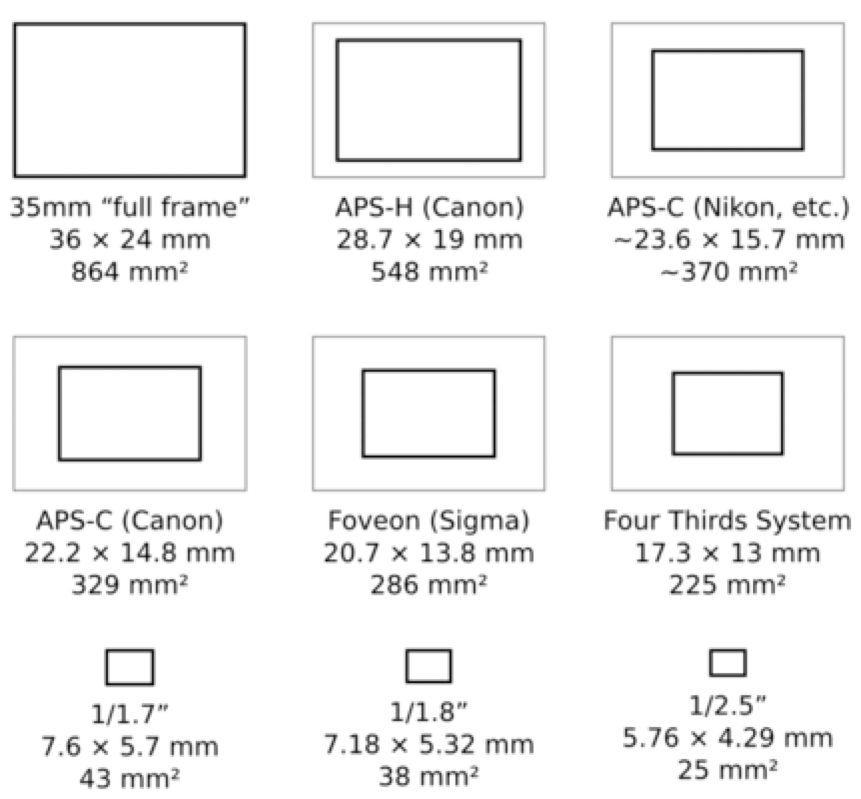
This guide uses 35 mm full frame as its main example, but the same proportion can be applied to other formats. Use the width of the active recorded image, not automatically the manufacturer’s total sensor width. Cropping, stabilization, open-gate capture, and delivery aspect ratio may change the relevant value.
Optional background: what the lens is doing
A lens bends incoming light so that a focused image forms on the sensor. The thin-lens model is a simplified way to describe this relationship. It pretends that all the bending happens at one infinitely thin plane.
If \(S_1\) is the distance from the object to the lens, \(S_2\) is the distance from the lens to the focused image, and \(f\) is focal length, the relationship is
\[ \boxed{\frac{1}{S_1}+\frac{1}{S_2}=\frac{1}{f}}. \]
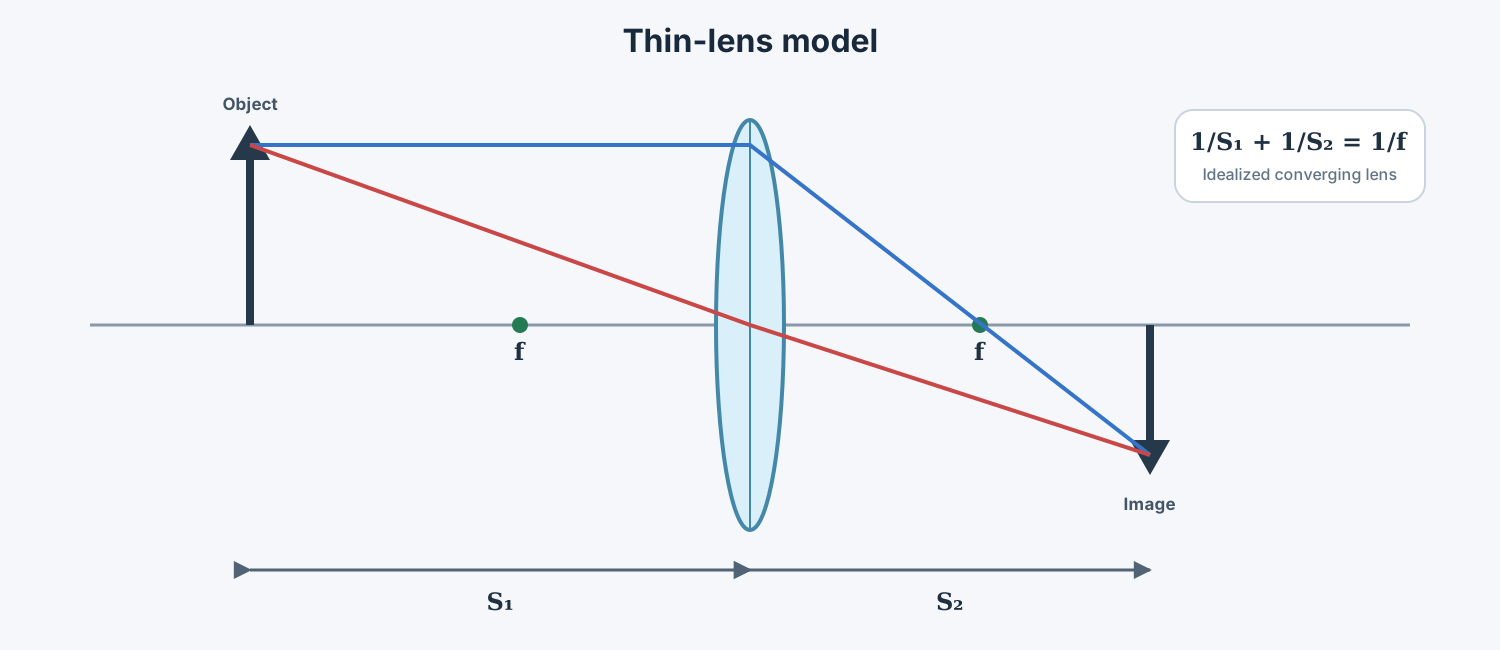
Real photographic lenses are compound optical systems, and their marked focal length and entrance-pupil position are simplifications. The thin-lens model is nevertheless useful for understanding why focal length, subject distance, and image displacement are linked.
The thin-lens formula provides the optical background. For the practical stereobase example below, you only need the focal length printed on the lens and the measured distance to the near object.
Turning those choices into camera spacing
We can now connect the allowed image offset to the physical spacing of the cameras. The diagram may look technical, but it describes a simple setup: two parallel cameras look toward the same near object. The top path represents the left-eye view and the bottom path the right-eye view.
For the specific geometry used here, assume:
- two parallel cameras
- identical lenses and image formats
- the near object lies on the intended stereo window
- the far object is effectively at infinity
- \(v\) is the selected maximum image offset
- all lengths use the same unit
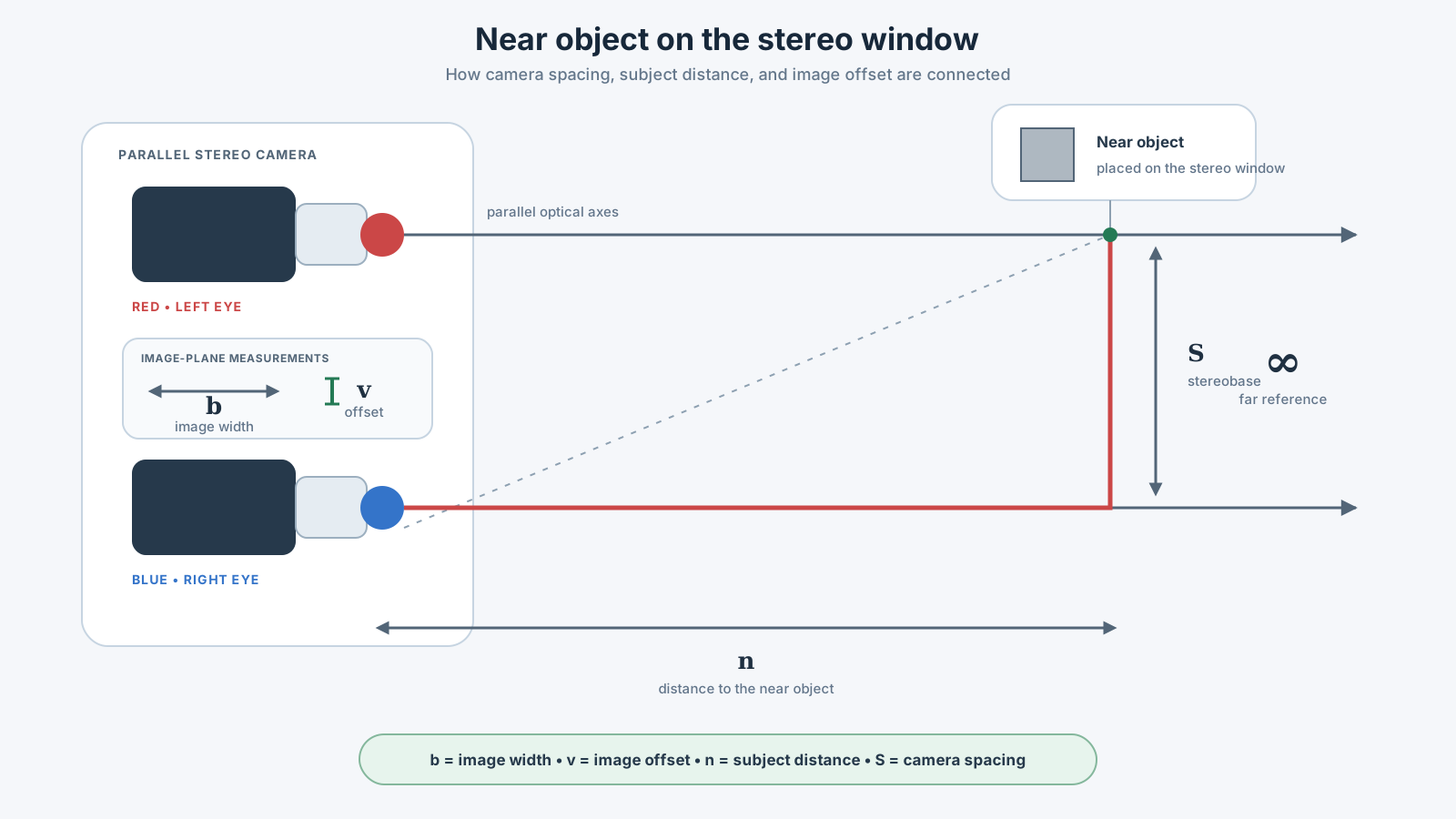
For this simple setup, the starting stereobase is
\[ \boxed{S=v\left(\frac{n}{f}-1\right)} \]
where:
| Symbol | Meaning | Typical unit |
|---|---|---|
| \(S\) | stereobase / interaxial camera spacing | mm |
| \(v\) | allowed offset in the captured image | mm |
| \(n\) | distance to the near object and stereo window | mm |
| \(f\) | focal length | mm |
Here is the same instruction without mathematical shorthand:
- Divide the near-object distance \(n\) by the focal length \(f\).
- Subtract 1.
- Multiply the result by the permitted image offset \(v\).
- The answer is the starting camera spacing \(S\).
You can understand the direction of the result even before using a calculator:
- Move the nearest subject farther away, and the permitted camera spacing grows.
- Use a longer focal length in this model, and the calculated spacing becomes smaller.
- Permit more left–right difference, and the calculated spacing grows.
- Let a subject move closer, and the starting camera spacing quickly becomes smaller.
Let us calculate one real setup
Let us calculate one complete example slowly. We want to plan a stereo shot for a 1.75 m-wide projected image. The nearest important object is 3.3 m from the cameras, and we use 50 mm lenses on full-frame cameras.
These are the starting values:
- Projection width — 1.75 m: how wide the finished picture will appear.
- Chosen screen separation — 6.25 cm: an example positive-parallax reference, close to a typical adult interpupillary distance, used to prevent a distant point from demanding excessive outward eye rotation.
- Recorded image width — 36 mm: the active width of the full-frame image.
- Focal length — 50 mm: the lens used by both cameras.
- Nearest important object — 3.3 m: nothing important should enter closer than this without recalculating.
- Far object — effectively infinity: the distant background is treated as extremely far away.
Step 1: shrink the screen limit to camera size
First, convert the chosen separation on the projection screen into the much smaller separation allowed in the recorded image:
\[ v = \frac{36\,\text{mm}\times62.5\,\text{mm}} {1750\,\text{mm}} =1.2857\,\text{mm}. \]
Rounded for practical use:
\[ v\approx1.28\,\text{mm}. \]
So the left- and right-eye versions of a distant point may be separated by about 1.28 mm across the recorded full-frame image under these assumptions.
Another way to say this is: 62.5 mm on the final screen corresponds to about 1.28 mm inside the recorded image.
Step 2: turn that offset into camera spacing
Next, use that image offset to calculate the distance between the cameras. All measurements are written in millimetres so the units remain consistent:
\[ \begin{aligned} S &=1.2857\left(\frac{3300}{50}-1\right)\text{mm}\\ &=1.2857(66-1)\text{mm}\\ &=83.57\,\text{mm}\\ &\approx8.36\,\text{cm}. \end{aligned} \]
The simplified result is therefore
\[ \boxed{S\approx8.3\,\text{cm}}. \]
In practical terms, the optical centres of the two cameras would begin about 8.3 cm apart. This is an initial setup value, not an instruction to start recording immediately. The scene must still be checked on a stereo monitor, especially if anything moves closer than 3.3 m.
The calculated base is slightly wider than the average distance between human eyes. That can be reasonable for this example, but a closer foreground object would require a new calculation and would usually reduce the camera spacing.
What to do on the actual shoot
The formula gives you a starting point. The production workflow turns that number into a safe shot:
- Decide where people will watch it. Note the expected screen or virtual display size.
- Find the closest important subject. Measure from the cameras, and allow for actors or objects that may move closer during the shot.
- Note the lens and recorded image width. Use the real capture settings, including any crop.
- Calculate a starting spacing. Treat the answer as a first setup, not a guarantee.
- Build and match the camera pair. Keep both cameras parallel, synchronized, and on matching settings.
- Look at the 3D image. Use a stereo monitor and check the nearest subject, distant background, and edges of the frame.
- Record a test. If the depth feels tiring, objects cannot be fused, or foreground objects cut awkwardly at the frame edge, reduce the spacing and test again.
Mark the cameras L and R, mark the recording media, keep focal length, focus, exposure, white balance, and frame timing matched, and preserve the eye designation in filenames—for example, 001_L and 001_R.
When you are ready to go deeper
This method gives you a way into the subject. It does not replace a complete depth budget or a production test. When the basic workflow feels comfortable, useful next topics include:
- near and far parallax limits rather than a single maximum value
- finite far-object distance
- depth-bracket and disparity-budget methods
- convergence and stereo-window placement
- percentage-based screen disparity
- retinal disparity and viewing-distance models
- camera entrance-pupil position
- lens distortion and focus breathing
- image cropping, scaling, and stabilization
- head-mounted displays and variable virtual screen geometry
- hyperstereo, macro stereo, and miniature subjects
- moving subjects and temporal synchronization
There is no single magical stereobase that works for every shot. The practical skill is learning which measurements matter, choosing a sensible starting point, and checking the result under the conditions in which people will actually watch it.