flowchart TD
    A["Build or capture a 3D scene"] --> B["Define the hologram image plane"]
    B --> C["Set viewing distance and field of view"]
    C --> D["Test foreground and background limits"]
    D --> E["Render a numbered sequence<br/>of perspective views"]
    E --> F["Convert views into hogels"]
    F --> G["Print the digital hologram"]
    G --> H["Evaluate depth, comfort,<br/>color, and viewpoint delivery"]
    H -. "adjust scene" .-> B

    classDef setup fill:#dcecff,stroke:#3d7db8,color:#17324d;
    classDef stereo fill:#fff0d5,stroke:#d0922d,color:#503712;
    classDef output fill:#e5f4ec,stroke:#45936b,color:#173d2a;
    class A,B,C setup;
    class D,E stereo;
    class F,G,H output;
Evaluating Stereoscopy in Digital Holography
Designing a reference test chart for comfortable and measurable holographic content
Holography
Stereo3D
How stereoscopic image principles can be used to design, measure, and evaluate content for printed digital holograms.
Keywords
digital holography, stereoscopy, parallax, viewing comfort, holographic test chart, Blender, hogel
1 Why stereoscopy matters to digital holography
NoteHolography and stereoscopy are not the same
Holography itself is a light-field and wavefront-reconstruction medium. A true hologram records or synthesizes optical information that allows the reconstructed scene to present continuously changing directional views. It is therefore not simply a stereoscopic image made from one fixed left-eye and one fixed right-eye picture.
This article is specifically about digital holographic stereograms created from a sequence of rendered perspective views. Stereoscopic principles are useful here as tools for evaluating what each pair of eyes receives at a given viewing position. They help identify disparity, depth-range, image-plane, occlusion, and viewing-comfort problems, but they do not fully describe the holographic light field.
A digital hologram is not simply a stereoscopic picture, but the viewer still observes it with two eyes. At every viewing position, the left and right eye receive two slightly different views. The pair changes as the observer moves, creating motion parallax and allowing the holographic scene to be inspected from different angles.
That means many principles developed for Stereo3D cinema, lenticular displays, and multiview imaging remain useful when creating holographic content:
- the position of the image plane;
- the usable space in front of the image;
- the comfortable depth behind the image;
- the relationship between viewpoint spacing and perceived scale; and
- the avoidance of conflicting or incomplete left- and right-eye images.
My 2022 study, “Evaluation of Stereoscopy in Digital Holography,” applied these principles to the construction of a measurable holographic reference scene (Hamacher 2022). The objective was not merely to produce an attractive hologram. It was to create a test chart that helps content creators and hologram printers see where a system’s usable three-dimensional space begins and ends.
Screen recording of the digital holography test material used to evaluate viewpoint changes and stereoscopic depth.
TipRead the complete research article
The full open-access paper is available from the International Journal of Engineering Trends and Technology.
Download the published PDF or open the article through its DOI.
2 From two views to many views
In conventional Stereo3D, a production usually prepares one left-eye and one right-eye image. A printed digital holographic stereogram uses a much larger set of perspective images. The printer reorganizes those views into hogels so that the observer receives the appropriate image pair at each position. These hogels are the directional, holographic analogy to pixels in a conventional image.
The analogy to stereoscopic production is powerful, but it is not exact. A fixed stereo pair follows the viewer regardless of their position. A hologram presents a different stereo pair as the viewer moves. The most extreme viewing positions can therefore reveal occlusion, border, disparity, or comfort problems that remain hidden from the central view.
3 The four parameters a test chart must reveal
3.1 1. Image plane
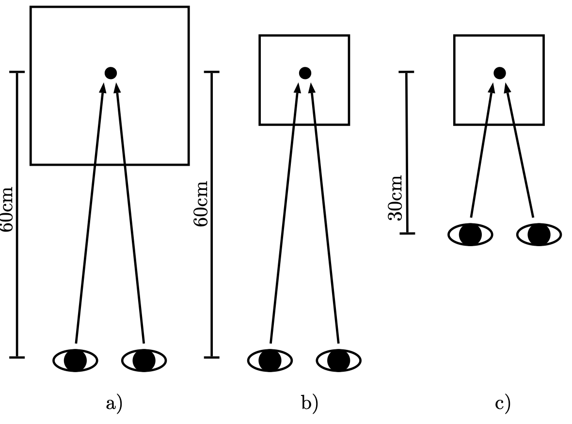
The image plane is the depth level at which left- and right-eye points have zero parallax. In a painting or photograph, the physical surface is obvious. In a stereoscopic or holographic image, the surface can disappear perceptually because objects extend in front of and behind it.
For the test chart, the image plane is represented by the physical center plane of the final hologram. Clearly marked objects at this depth provide a stable zero-parallax reference. Without it, a content creator cannot reliably describe whether another object lies 20 cm behind the plate or appears to emerge 10 cm in front of it.
3.2 2. Frontmost plane
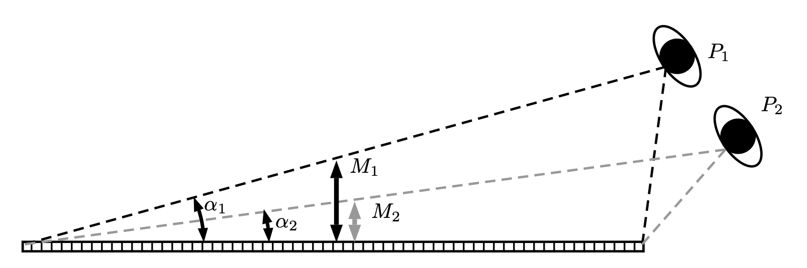
Objects placed in front of the hologram use negative parallax and can create the attractive impression of emerging into the viewer’s space. The available foreground is nevertheless finite.
At an oblique viewpoint, the opposite edge of the hologram begins to occlude the reconstructed object. One eye may still see the object while the other eye sees it cut by the frame. In stereoscopic cinema this is known as a stereo window violation. In a hologram it can occur only at some viewing positions, which makes the complete viewing arc important during evaluation.
3.3 3. Background plane
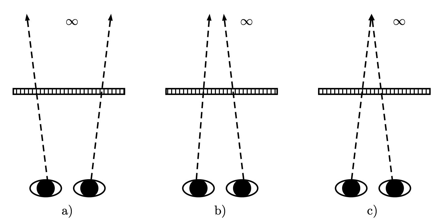
The rear of the holographic scene is not automatically comfortable simply because it appears behind the image plane. Very large disparities can require the eyes to diverge. Even before divergence occurs, the viewer may experience a strong vergence-accommodation conflict: the eyes converge on a virtual point behind the plate while focusing on light associated with the plate.
The acceptable range depends on image size and viewing distance. A postcard- sized hologram viewed from nearby should not casually represent “infinity” with the same geometry as a cinema screen. The test chart therefore places labeled objects at known depths rather than relying on an unmeasured background.
3.4 4. Viewpoint identification
A viewer does not directly know which two rendered frames reach their eyes. The test sequence therefore embeds a visible frame number in every perspective image. When the printed hologram is observed, those numbers identify the delivered views and reveal how the printer maps source frames across its viewing field.
This makes the chart useful for more than artistic judgment. It can expose missing, repeated, reversed, unevenly spaced, or poorly aligned viewpoints.
4 Building the Blender reference scene
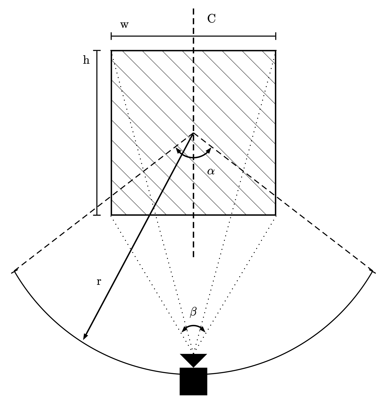
The reference scene was built in Blender to give exact control over geometry, camera movement, color, lighting, and labels. The physical hologram was defined as a 30 × 40 cm image plane centered on the scene origin.
The virtual camera was positioned one metre from the center of the hologram and constrained to rotate around its vertical convergence axis. Its field of view matched the hologram height. A 120° printing field was sampled from -60° to +60°.
| Parameter | Meaning | Test-chart value |
|---|---|---|
| \(w\) | Hologram width | 30 cm |
| \(h\) | Hologram height | 40 cm |
| \(r\) | Camera and intended viewer distance | 1 m |
| \(\alpha\) | Total hologram viewing angle | 120° |
| \(\varphi\) | Camera’s horizontal field of view | 22.6° |
| \(C\) | Convergence axis | Scene origin |
| \(n\) | Number of horizontal viewpoints | 768 |
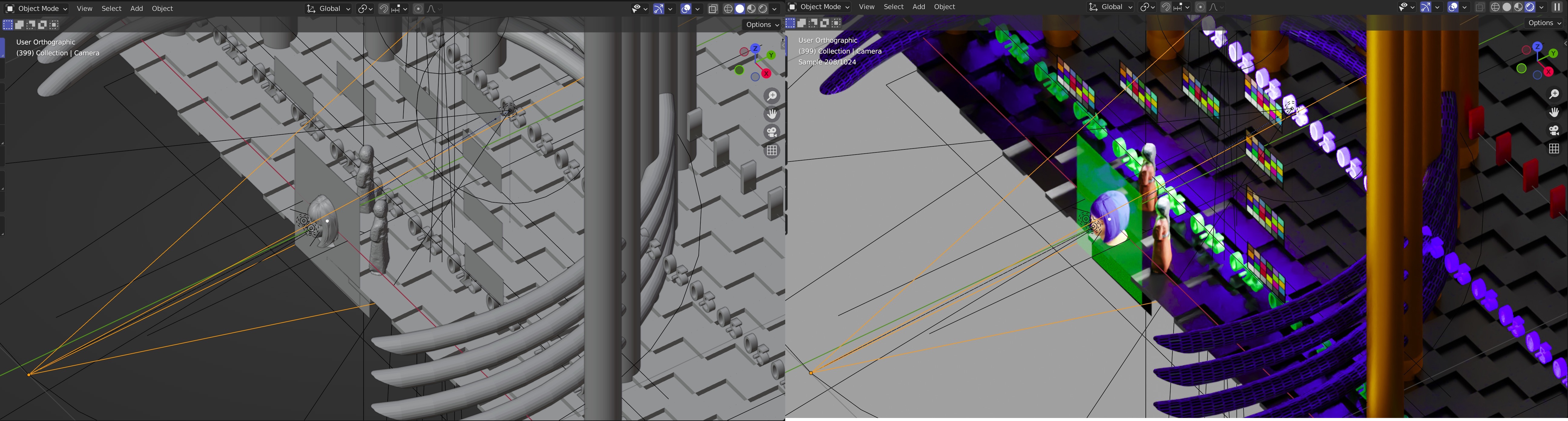
4.1 What the scene contains
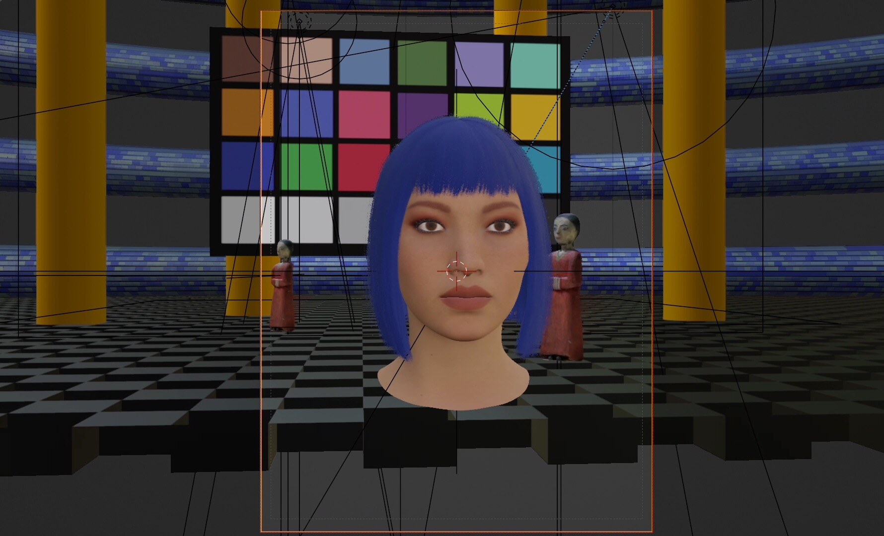
The final scene combines measurement objects with visually demanding material:
- numbered viewpoints on the image plane;
- a photorealistic human head for skin, hair, and facial detail;
- color charts for color and exposure evaluation;
- a checkerboard floor with 10 × 10 cm tiles;
- scanned figures at controlled distances;
- columns and text labels marking rear depth; and
- a surrounding textured tube at one metre behind the image plane.
| Reference object | Position relative to image plane |
|---|---|
| Head center and viewpoint numbers | 0 cm |
| Right figure | 20 cm behind |
| Left figure | 30 cm behind |
| “0.25” labels | 25 cm behind |
| “0.5” labels and center color chart | 50 cm behind |
| “1” labels and center columns | 100 cm behind |
5 Rendering the hologram input
The camera animation produced 768 horizontal perspective images covering the 120° arc. Each frame was exported as a 16-bit RGB PNG. The sequence was designed for a horizontal-parallax hologram: the camera changes horizontally while its distance, convergence target, and framing remain controlled.
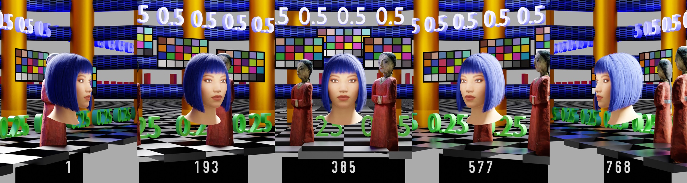
The five examples in Figure 7 make the purpose of the chart visible: near objects move rapidly across the frame, distant objects move more slowly, the central view is symmetrical, and the embedded number identifies the exact source image.
6 What can be evaluated
After the image sequence is converted into hogels and printed, the resulting hologram can be inspected for:
- Image-plane registration — whether the zero-parallax markers remain stable at the intended plate surface.
- Usable foreground — how far an object can emerge before the border creates an occlusion or stereo window violation.
- Comfortable background — which labeled rear depths remain easy to fuse at the intended viewing distance.
- View delivery — whether the numbered source frames appear in the correct order and spacing across the viewing arc.
- Printing quality — color rendition, exposure, sharpness, fine detail, depth continuity, and transitions between views.
Because the geometry is measured, a problem can be described precisely. A creator can say that the 50 cm background marker exceeds the comfortable range, for example, instead of merely reporting that the image “feels too deep.”
The same source sequence can also be printed with different hologram sizes, viewing distances, or printer technologies. It therefore provides a basis for comparative testing rather than evaluating each hologram with unrelated content.
7 Practical lessons for content creators
The research leads to four useful production rules:
- Design for the final plate and viewer distance. The camera geometry should not be chosen independently from the physical hologram.
- Inspect the complete viewing field. A scene that works centrally may fail at the edge of the viewing arc.
- Treat depth as a limited creative volume. Foreground and background space both have perceptual and geometric boundaries.
- Keep measurable references in technical tests. Frame numbers, known distances, color charts, and detailed objects make faults diagnosable.
These ideas connect holographic content creation directly to established Stereo3D practice. Holography adds many viewpoints and a different optical recording method, but it does not remove the human visual system from the production pipeline.
8 Publication
The research was published open access in the International Journal of Engineering Trends and Technology, Volume 70, Issue 12, pages 345–350, on 24 December 2022 (Hamacher 2022).
Alaric Hamacher, “Evaluation of Stereoscopy in Digital Holography,” International Journal of Engineering Trends and Technology 70(12), 345–350 (2022). DOI: 10.14445/22315381/IJETT-V70I12P233.
9 References
Hamacher, Alaric. 2022. “Evaluation of Stereoscopy in Digital Holography.” International Journal of Engineering Trends and Technology 70 (12): 345–50. https://doi.org/10.14445/22315381/IJETT-V70I12P233.