Photogrammetry: From Photographs to 3D
Feature matching, epipolar geometry, VisualSFM, and Apple RealityKit Object Capture
photogrammetry, Structure from Motion, SIFT, fundamental matrix, epipolar geometry, VisualSFM, RealityKit, Object Capture

Recovering depth from photographs
A photograph records a three-dimensional scene on a flat sensor. Depth is lost: a small nearby object and a large distant object can occupy the same number of pixels. Photogrammetry recovers that missing structure by comparing many overlapping photographs.
The central clue is parallax. As a camera moves, nearby features shift more strongly than distant features. If software can recognize the same physical point in several images, it can estimate where the cameras were and where that point must be in 3D space. Thousands or millions of such observations eventually become a point cloud, surface, and textured model.
The lecture below develops this idea from theory to practice. It demonstrates a classic VisualSFM reconstruction and Apple’s RealityKit Object Capture workflow.
Transfer camera files directly whenever possible. Messaging applications may resize images, increase compression, or strip EXIF metadata. Original resolution, focal-length information, sharp detail, and consistent exposure all help the reconstruction.
The reconstruction pipeline
Photogrammetry is not one mysterious operation. It is a sequence of increasingly geometric decisions:
- Detect distinctive points in each photograph.
- Describe and match those points between overlapping images.
- Reject false matches using two-view geometry.
- Estimate cameras and sparse structure with Structure from Motion (SfM).
- Refine everything together using bundle adjustment.
- Densify, mesh, and texture the scene using multi-view stereo and the original photographs.
The first three stages deserve special attention. If the correspondences are wrong, every later calculation is built on the wrong evidence.
Finding the same place twice
Feature points
A useful feature is a small, locally distinctive pattern: a corner of a label, a crack in stone, the junction between two edges, or a textured spot on fabric. It should remain recognizable when the camera moves, rotates, or changes scale.
Feature processing has two related jobs:
- a detector decides where stable points are located;
- a descriptor turns the neighborhood around each point into numbers that can be compared efficiently.
Flat walls, transparent glass, moving foliage, repeating grids, and shiny reflections are difficult because they contain too little stable visual evidence or change their appearance between viewpoints.
SIFT: a durable visual fingerprint
David Lowe’s Scale-Invariant Feature Transform (SIFT) became a foundational method for local feature detection and description (Lowe 2004). Its main stages are easier to understand than the name suggests:
- Search at several scales. A feature may be small in one image and large in another. SIFT searches a scale space rather than only the original image.
- Keep stable extrema. Difference-of-Gaussian images reveal local peaks and valleys; weak edge-like responses are rejected.
- Assign an orientation. The dominant local gradient gives the feature a repeatable direction, making the description resistant to image rotation.
- Describe the neighborhood. Local gradient orientations are collected in small spatial cells, producing a 128-value descriptor.
Two descriptors that look similar are potential matches—not proven matches. The nearest alternative is compared as well, and geometric verification such as RANSAC removes pairs that do not agree with a shared camera relationship.
SIFT says that two patches look alike. Epipolar geometry asks whether they could be observations of the same 3D point from two cameras.
The fundamental matrix
Take two photographs from different positions. A visible scene point (X) appears at pixel (x) in the left image and at (x’) in the right image. Once (x) is known, its possible match in the other image is not anywhere on that image: it must lie on a particular epipolar line.
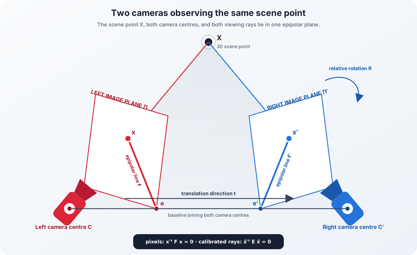
The fundamental matrix (F) is the (3) matrix that expresses this relationship in image-pixel coordinates (Hartley and Zisserman 2004):
\[ \boxed{\mathbf x'^{\mathsf T}\,\mathbf F\,\mathbf x = 0} \]
Here (x=[u,v,1]^{T}) and (x’=[u’,v’,1]^{T}) are pixel positions written in homogeneous coordinates. The formula can be read in two simple steps:
\[ \mathbf l' = \mathbf F\mathbf x \qquad\text{and}\qquad \mathbf x'^{\mathsf T}\mathbf l'=0. \]
First, (F) maps the left-image point to the right-image line (l’). Second, the true right-image match must sit on that line. The reverse mapping is (l=F^{T}x’).
Why this matrix matters
Without geometry, matching one feature requires searching an entire two-dimensional image. With a reliable fundamental matrix, the plausible region collapses to a one-dimensional line. This makes matching faster and exposes outliers whose locations are inconsistent with the two cameras.
The same constraint supports many forms of visual computation:
- robust correspondence filtering;
- recovery of relative camera motion;
- triangulation of 3D points;
- stereo rectification and depth estimation;
- Structure from Motion, visual odometry, SLAM, robotics, and spatial computing.
The matrix does not contain a finished 3D model. It summarizes projective geometry between two views and is defined only up to scale. It normally has rank two and is estimated from several correspondences—commonly with a normalized eight-point method inside RANSAC.
Fundamental matrix or essential matrix?
The two names refer to closely related matrices, but not to the identical coordinate system:
- the fundamental matrix (F) relates ordinary pixel coordinates;
- the essential matrix (E) relates calibrated, normalized camera rays after the lens intrinsics have been removed.
For camera calibration matrices (K) and (K’), their relation is
\[ \mathbf E=\mathbf K'^{\mathsf T}\mathbf F\mathbf K. \]
The essential matrix encodes the relative camera rotation (R) and the direction of translation (t). It is therefore the form used when the cameras are calibrated and their relative pose must be recovered.
From matches to a model
Once a stable starting pair is found, the software triangulates matched points and creates a sparse reconstruction. Additional photographs are registered against that structure. New 3D points are added as the camera network grows.
Bundle adjustment then refines camera poses, camera parameters, and 3D points together (Wu et al. 2011). It minimizes reprojection error: the distance between an observed feature and the pixel where the current 3D solution predicts that feature should appear.
Sparse points are excellent for solving cameras but do not yet form a surface. A later multi-view stereo stage searches more densely across the images. The resulting dense cloud can be converted to a polygon mesh and textured from the original photographs.
VisualSFM: watching SfM happen
VisualSFM by Changchang Wu was one of the pioneering systems that made a complete Structure-from-Motion workflow visible and usable through a graphical interface. Wu describes the experience succinctly:
“Reconstruct 3D with a few button clicks, and watch the dynamic reconstruction process!”
The application integrates GPU-accelerated SIFT detection and matching, incremental SfM, Multicore Bundle Adjustment, and external CMVS/PMVS tools for dense reconstruction. Its concise interface exposes four practical stages.
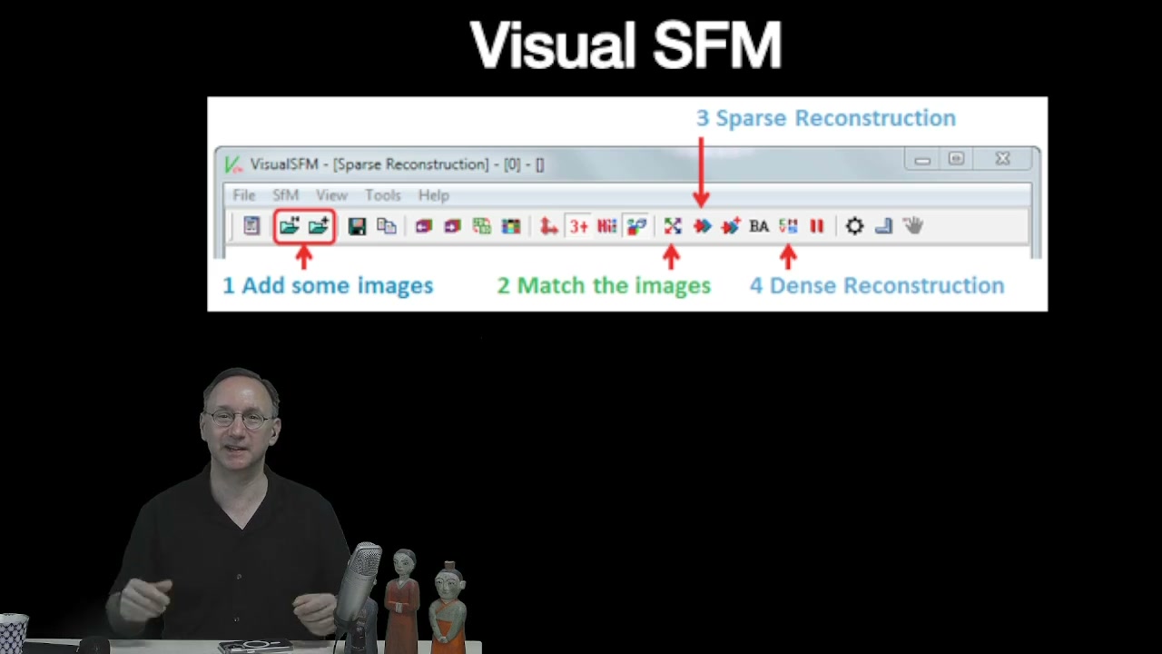
- Add photographs. VisualSFM reads the images and available camera metadata.
- Match images. SiftGPU detects and compares local features across plausible image pairs.
- Run sparse reconstruction. Incremental SfM estimates cameras, triangulates points, and repeatedly adjusts the solution.
- Run dense reconstruction. CMVS/PMVS expands the sparse geometry into a much denser point cloud.
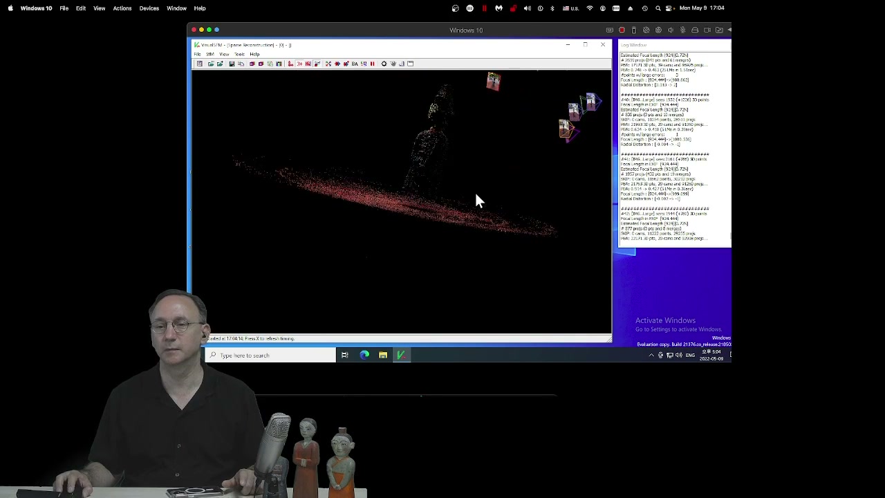
VisualSFM is available from the author’s project page, along with its documentation, binaries, and NVM file-format information. It is legacy software and its GPU dependencies can require an older or carefully prepared workstation, but it remains educationally valuable because the camera solve is visible rather than hidden behind an upload service.
Wu’s own README asks publications using VisualSFM to cite either the 2013 incremental SfM paper (Wu 2013) or the VisualSFM system (Wu 2011), together with Multicore Bundle Adjustment (Wu et al. 2011).
Apple RealityKit Object Capture
Apple’s current photogrammetry framework is RealityKit Object Capture—not a generic ARKit operation. On supported Apple platforms, PhotogrammetrySession processes a directory of overlapping photographs and can produce a USDZ model, poses, bounds, and point-cloud results (Apple Developer, n.d.).
The session model is deliberately compact:
- select an input directory containing original photographs;
- create a
PhotogrammetrySession; - submit one or more requests, such as a model-file request;
- monitor the asynchronous
outputssequence for progress, completion, or errors; - inspect and refine the resulting USDZ asset.
guard PhotogrammetrySession.isSupported else {
    fatalError("Object Capture is not supported on this device")
}

let session = try PhotogrammetrySession(input: imageDirectory)
let request = PhotogrammetrySession.Request.modelFile(
    url: outputURL,
    detail: .medium
)

try session.process(requests: [request])

for try await output in session.outputs {
    switch output {
    case .requestProgress(_, let fraction):
        print("Progress: \(fraction)")
    case .requestComplete(_, let result):
        print("Completed: \(result)")
    default:
        break
    }
}
The model request offers detail levels from quick previews through reduced, medium, full, and raw output. A session configuration can adjust sample ordering, feature sensitivity, object masking, checkpoint behavior, and mesh primitives. These are useful controls, but they cannot repair missing viewpoints, motion blur, or a surface with no stable texture.
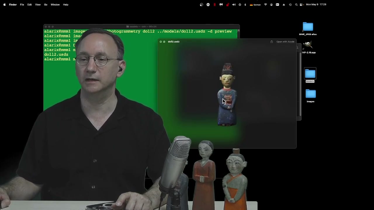
Apple provides the current API reference for PhotogrammetrySession, its Request types, Output stream, and model Detail levels.
A practical capture pattern
For a small object, begin with a simple, repeatable path:
- use diffuse, stable light and keep the object motionless;
- lock focus and exposure when the device allows it;
- fill the frame without cutting off the subject;
- photograph a complete ring with strong overlap;
- repeat from a higher and a lower angle to cover the top and underside;
- add close views of weakly textured or geometrically important regions;
- inspect every image for blur before reconstruction;
- preserve original files and metadata.
More photographs are useful only when they add clear, overlapping evidence. Fifty sharp, well-spaced views can be more valuable than hundreds of blurred or nearly identical images.
Can you point to the same small detail in at least three photographs? If a region is visible only once, the software has no reliable geometric evidence from which to reconstruct it.