flowchart LR
    A["Eight rendered or captured views"] --> B["Quartz Composer image inputs"]
    B --> C["multiplyEffect kernel"]
    C --> D["RGB subpixel multiplexed raster"]
    D --> E["Alioscopy LCD + lenticular array"]
    E --> F["View-dependent stereo perception"]

    classDef source fill:#dcecff,stroke:#3d7db8,color:#17324d;
    classDef process fill:#fff0d5,stroke:#d0922d,color:#503712;
    classDef display fill:#e5f4ec,stroke:#45936b,color:#173d2a;
    class A,B source;
    class C,D process;
    class E,F display;
Multiview Shader with Subpixels
My independent Quartz Composer work for eight-view glasses-free 3D
Holography
The story and annotated code of Alaric Hamacher’s independent eight-view Alioscopy shader work in Quartz Composer.
Keywords
Alioscopy, Pierre Allio, autostereoscopic display, lenticular display, Quartz Composer, Core Image kernel, subpixel multiplexing, multiview rendering
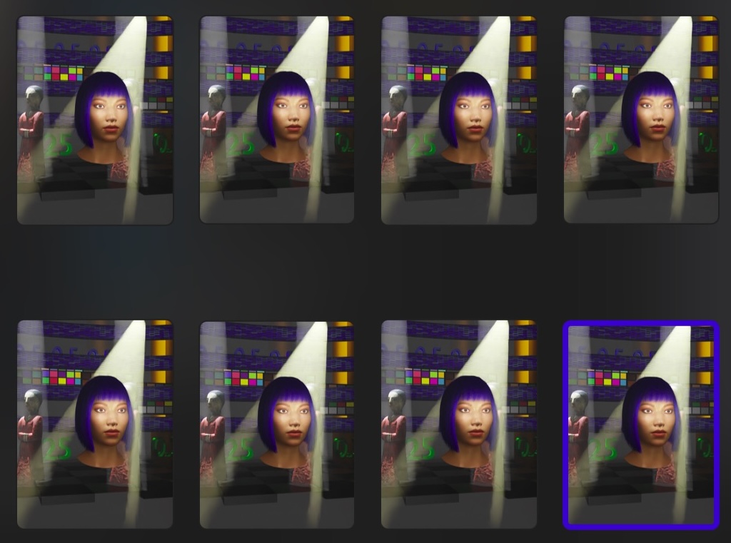
1 My Alioscopy shader
I developed ALIOSC_MIX8.qtz as part of my work introducing Alioscopy glasses-free 3D displays in Germany. It was a practical shader for a practical problem: how can eight carefully prepared views be transformed into the single subpixel-multiplexed image required by an Alioscopy lenticular display?
The software development was independent. I developed the Quartz Composer composition and shader implementation without a connection to Pierre Allio or to Alioscopy’s internal software development. The work was designed to drive Alioscopy displays and to conform to their documented optical requirements, but the programming itself was my own independent technical work.
This was not an academic exercise separated from production. We demonstrated Alioscopy systems to customers including BMW and Louisenthal, the paper manufacturer in Bavaria. Each demonstration exposed the same truth: a multiview display is only as convincing as the entire chain connecting content, shader, panel, and lenticular optics.
The composition contains a QCImageKernel named multiplyEffect. Its job is not to render a 3D scene. It performs the final display-side operation: it selects samples from eight input images and places their color components into the subpixel pattern expected by an Alioscopy lenticular panel.
This distinction is important. The eight views must already exist. The kernel is a multiplexer, not a camera rig, depth estimator, or multiview renderer. It converts eight prepared views into one image whose RGB subpixels are arranged for the lenticular optical layer.
2 Alioscopy and Pierre Allio
Alioscopy is a French autostereoscopic-display company founded by Pierre Allio. Alioscopy’s own historical account places the founding principles of its digital autostereoscopy in 1986, its first patent in 1987, and the founding of the company in 1999. Its licensing page identifies Allio as the founder and president and describes a patent portfolio covering critical parts of the technology.
Pierre Allio belongs among the pioneers of glasses-free 3D displays because his work connected several parts of the system: multiview capture, view multiplexing, precision lenticular optics, and display calibration. That is a more useful historical description than treating autostereoscopy as a single screen accessory. The display, the lens array, and the image-generation grammar have to be designed as one system.
Alioscopy’s displays remain unusually distinctive. Their lenticular arrays are engineered for the physical pixel geometry of a specific panel, while their content encodes multiple perspectives into one raster image. The company describes its current systems as using proprietary algorithms and precision lenticular arrays manufactured in France. The claim that the displays are “unequaled” is an aesthetic and experiential judgment; the measurable reasons for their reputation are the optical precision, brightness-preserving lenticular approach, and carefully specified multiview geometry.
Sources: Alioscopy history, Alioscopy technology, Alioscopy licensing and Pierre Allio, and Alioscopy FAQ.
3 Introducing Alioscopy in Germany
I introduced Alioscopy displays in Germany at a time when glasses-free 3D was still often treated as a promise rather than as a reliable professional tool. The customer work made the technology concrete. BMW was interested in the impact of spatial presentation for design and communication. Louisenthal in Bavaria brought a different industrial context: a paper manufacturer whose work is closely connected to high-quality printed and security imagery.
For these audiences, the display had to work immediately. A multiview image that looked correct on an ordinary monitor was not automatically correct on the Alioscopy panel. ALIOSC_MIX8.qtz was the bridge between the eight-view content set and the physical subpixel/lens geometry of the display.
3.1 A stereoscopic Christmas greeting from 2009
The period is also represented by a 2009 Christmas greeting that we produced for Alioscopy in stereoscopic 3D. It captures the creative and technical character of the work: Alioscopy was presented not merely as a display, but as a medium for authored, glasses-free multiview experiences.
Watch the 2009 Alioscopy stereoscopic Christmas greeting on YouTube.
The composition is therefore best understood as production infrastructure. It is a small, inspectable piece of a larger pipeline:
4 Quartz Composer as my shader laboratory
Quartz Composer gave me a visual programming environment in which image sources, resizers, transforms, controls, and custom image processing could be connected as a live composition. I used that environment to develop and test ALIOSC_MIX8.qtz while the display pipeline was being demonstrated in Germany.
The visual graph handled the production plumbing: eight image inputs, their dimensions and transforms, the invert and offset controls, and the final image output. Inside the custom QCImageKernel, I could program the part that needed exact pixel-level control. This combination was powerful because the display geometry could be tested interactively while the multiplexing rule remained explicit in shader code.
The language is Core Image Kernel Language, Apple’s shader dialect for custom Core Image kernels. It resembles a constrained form of GLSL and uses the Core Image functions destCoord(), samplerCoord(), and sample() to calculate and fetch image data. It is not a general-purpose 3D language: the kernel receives images and produces pixels.
5 Programming the Quartz Composer kernel
I wrote the kernel around eight samplers and two scalar controls:
- 1
- The first four samplers carry four of the eight prepared viewpoints.
- 2
- The second four samplers complete the view set.
- 3
-
invertreverses view order;offsetadjusts horizontal registration.
Each sampler represents one prepared viewpoint. The output is one vec4, but the three color channels are not selected in the same phase. That is the key subpixel operation.
5.1 Create an 8×8 repeating address pattern
The shader reads the destination coordinate and reduces both coordinates modulo eight:
- 1
-
modyrepeats the address pattern every eight rows. - 2
-
modxrepeats it every eight columns. - 3
- The factor three advances the phase across the RGB subpixel sequence.
- 4
-
invertreverses the view order when the display orientation requires it.
mody repeats the pattern vertically. modx repeats it horizontally. The factor 3.0 advances the phase across the horizontal subpixel sequence; the modulo operation folds the result into eight view indices. The exact phase is not arbitrary: it is part of the display-specific relationship between the LCD subpixels and the slanted cylindrical lenses.
The invert input reverses the eight-index order. In practice, that gives the composition a way to compensate for an orientation or installation that requires the view order to be reversed.
5.2 Offset the eight samplers
The kernel then shifts the sample coordinate of each input horizontally:
- 1
- The first view is shifted four integer steps in one direction.
- 2
- The second view is shifted three steps toward the centre.
- 3
- The third view is shifted two steps toward the centre.
- 4
- The fourth view is shifted one step toward the centre.
- 5
- The fifth view begins the opposite side of the symmetric arrangement.
- 6
- The sixth view is shifted two steps in the opposite direction.
- 7
- The seventh view is shifted three steps in the opposite direction.
- 8
- The eighth view is shifted four integer steps in the opposite direction.
The center input has no shift. The other views are displaced symmetrically around it. Because the value is passed through floor, the control behaves as an integer step rather than a continuous subpixel translation. The composition exposes this as an offset control; its practical purpose is to adjust the horizontal registration of the view set before the final raster is sent to the display.
5.3 Select a view for each color component
The source repeats the selector logic for blue, green, and red. In simplified form, the blue calculation is:
- 1
-
The first prepared view contributes its blue channel when
sel1is active. - 2
- The second view is sampled at its registered coordinate.
- 3
- The third view occupies the next possible selector position.
- 4
- The fourth view is part of the same eight-way sum.
- 5
- The fifth view completes the first half of the view set.
- 6
- The sixth view continues the selector sequence.
- 7
- The seventh view is sampled without changing the output coordinate.
- 8
- The eighth view completes the blue-channel selection. Only one selector is active for a given phase; the same structure is repeated for green and red.
Only one selector is one at a time, so only one of the eight blue samples contributes to the output blue channel. The same structure is repeated for green and red, but the shader decrements and wraps submod between channel calculations. Consequently, one output pixel does not simply contain the same view in red, green, and blue. Its three subpixels can carry color components from different members of the eight-view set.
The result is assembled explicitly:
- 1
- Allocate the output pixel returned by the image kernel.
- 2
- Write the selected red component.
- 3
- Write the selected green component.
- 4
- Write the selected blue component.
- 5
- Set the output alpha to opaque.
- 6
- Return the assembled subpixel-multiplexed pixel.
That is the core of the Alioscopy mix: the input views are not tiled as eight ordinary images; their color components are interleaved according to the display’s subpixel/lens phase.
6 The power of the GPU
The achievement was not simply that the code selected eight images. The important step was expressing the selection as a GPU image kernel. Core Image can evaluate the same routine across the output raster: every output pixel reads its own destination coordinate, calculates its own phase, samples the required input images, and writes its own RGB result.
That makes the work radically different from a CPU routine that walks through the image in a serial loop. The arithmetic is regular, the coordinate pattern is local, and the eight inputs can remain available as image samplers while many output pixels are processed in parallel. For a large Alioscopy raster, this is what turns subpixel multiplexing from an impractical per-pixel bookkeeping task into a display pipeline that can operate interactively.
The archived composition contains no GPU model or benchmark, so it would be wrong to attach a measured frame rate to this shader. The defensible technical claim is architectural: I formulated the Alioscopy encoding as a parallel per-output-pixel operation. Actual throughput depends on image size, texture transfers, scaling and compositing around the kernel, the Core Image context, and the GPU generation.
Apple describes CIKernel as a GPU-based image-processing routine and defines the same coordinate-and-sample pattern used here. My work was to adapt that general mechanism to the exact eight-view subpixel grammar of Alioscopy.
7 Why eight views?
Alioscopy’s FAQ explains the design trade-off directly. Eight views provide seven neighboring stereo pairs and a lateral sweet spot of approximately 45.5 cm in the company’s described configuration. As a viewer moves laterally, the visible stereo pair changes, producing motion parallax rather than one fixed stereoscopic pair.
The same FAQ states that a Full HD Alioscopy panel has 1,920 × 1,080 pixels, with three subpixels per pixel, and describes 720 cylindrical microlenses when each lens covers eight horizontal subpixels. This is the physical reason a shader cannot be designed from the nominal LCD resolution alone: the content must match the lens pitch, slant, panel geometry, and intended view order.
The eight-view choice is a compromise. More views can enlarge the usable viewing region, but they also divide the available display sampling more finely. Alioscopy describes eight views as a balance between continuous lateral motion parallax and the sharpness available from an HD panel.
8 What this shader does
| Operation | ALIOSC_MIX8.qtz |
|---|---|
| View inputs | Eight image samplers for the prepared viewpoints |
| View selection | An 8×8 coordinate pattern with channel phase rotation |
| Color handling | Independent red, green, and blue subpixel selection |
| Registration | Integer horizontal offsets controlled by offset |
| Orientation | View-order reversal controlled by invert |
| Output | One RGB raster with alpha set to 1.0 |
The composition brings these operations together into a coherent production tool: eight views enter the Quartz Composer graph, the kernel calculates their subpixel phases, and the multiplexed raster is prepared for the Alioscopy display.
9 A small historical artifact with a precise job
The value of ALIOSC_MIX8.qtz is that it makes a normally invisible stage of autostereoscopic production inspectable. The viewer sees a single image on the screen. Behind that image are eight views, a repeating subpixel address pattern, three phase-shifted channel selections, and a lenticular sheet whose geometry determines where the light travels.
During the German introduction of Alioscopy displays, this kind of shader was the practical meeting point between image-making and display engineering. It translated the creative desire for a moving, glasses-free 3D scene into the specific raster grammar of a Pierre Allio display.
The shader is not a generic “3D effect.” It is a device-specific encoding step: small in source code, but essential to the relationship between eight views and the display’s physical subpixels.
10 Sources
- Alioscopy — company history and Pierre Allio
- Alioscopy — technology and 8-view multiplexing
- Alioscopy — frequently asked questions
- Alioscopy — licensing, patents, and Pierre Allio
- Dassault Systèmes — Alioscopy partner profile
- Archived composition:
ALIOSC_MIX8.qtz, containing the Quartz Composer graph and embeddedQCImageKernelsource.