flowchart TD
    A["Original post-production files<br/><small>graded picture • final audio • subtitles • metadata</small>"]
    B["Digital Source Master — DSM<br/><small>completed creative master</small>"]
    C["Digital Cinema Distribution Master — DCDM<br/><small>standardized cinema picture • audio • subtitles</small>"]
    D["Cinema encoding and packaging<br/><small>JPEG 2000 • MXF wrapping • optional encryption</small>"]

    E["Picture Track File<br/><small>JPEG 2000 in MXF</small>"]
    F["Sound Track File<br/><small>PCM audio in MXF</small>"]
    G["Subtitle Track File<br/><small>timed text, fonts, and images</small>"]

    H["CPL — Composition Playlist<br/><small>reel order, timing, and asset references</small>"]
    I["PKL — Packing List<br/><small>package inventory, sizes, and hashes</small>"]
    J["AssetMap + VOLINDEX<br/><small>physical file locations and package volume</small>"]
    K["Complete DCP folder<br/><small>validated and ready for cinema delivery</small>"]
    L["Cinema server<br/><small>ingest • validate • decrypt • play</small>"]
    M["KDM<br/><small>separate key for encrypted playback</small>"]

    A --> B --> C --> D
    D --> E
    D --> F
    D --> G
    E --> H
    F --> H
    G --> H
    H --> I --> J --> K --> L
    M -. authorizes .-> L

    classDef source fill:#e8f1ff,stroke:#2f74c0,color:#16385e,stroke-width:2px;
    classDef master fill:#f1eaff,stroke:#7651b5,color:#392364,stroke-width:2px;
    classDef process fill:#fff2d9,stroke:#d58a16,color:#5f3a00,stroke-width:2px;
    classDef essence fill:#e7f7ef,stroke:#2f8f62,color:#174b35,stroke-width:1.5px;
    classDef document fill:#f7f9fc,stroke:#748296,color:#273444,stroke-width:1.5px;
    classDef delivery fill:#e7f5ff,stroke:#1677a8,color:#0b405d,stroke-width:2px;

    class A,B source;
    class C master;
    class D process;
    class E,F,G essence;
    class H,I,J document;
    class K,L,M delivery;
Spatial Reality Display
Concepts and technical terms used throughout the book.
This glossary collects the core concepts used throughout the book. Links from the chapters lead directly to the relevant term below.
Stereo Window
The stereo window is the apparent plane through which a viewer sees a stereoscopic scene. In a cinema it normally coincides with the physical screen; on a television it coincides with the display surface; and in a headset it may correspond to a virtual display plane defined by the presentation system.
Imagine that the display is not a flat picture but an opening in a wall. Some objects appear behind the opening, some touch its surface, and some seem to extend through it toward the audience. That imagined opening is the stereo window.
NoteShort definition
The stereo window is the depth plane where corresponding points in the left and right images have zero horizontal separation on the display.
The window as a depth reference
The stereo window divides the perceived scene into three regions:
| Position | Image relationship | What the viewer perceives |
|---|---|---|
| In front of the window | Negative parallax | The object appears to project toward the audience |
| On the window | Zero parallax | The object appears to sit on the display surface |
| Behind the window | Positive parallax | The object appears to recede behind the display |
These terms use the common digital-cinema convention. Some technical fields use different sign conventions, so it is always sensible to state what “positive” and “negative” mean in a particular document or application.
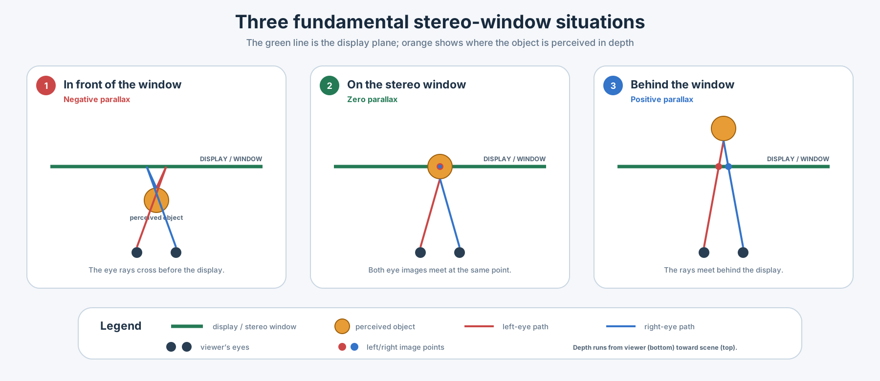
Zero parallax
Choose one visible point in the scene and compare its horizontal position in the left and right images.
If the point appears at the same screen position for both eyes, it has zero parallax. The viewer therefore perceives it on the stereo window. This is why the stereo window is also called the zero-parallax plane or screen plane.
Zero parallax does not mean that the scene has no depth. It simply identifies the reference plane from which depth is perceived in front or behind.
Negative parallax: in front of the window
With negative parallax, the left- and right-eye rays cross between the viewer and the display. The object therefore appears to float in front of the screen.
This can create a strong and exciting effect, but it consumes part of the viewer’s comfort budget. Large foreground parallax, fast motion, or an object very close to the viewer can make fusion difficult.
Positive parallax: behind the window
With positive parallax, the corresponding left- and right-eye points are separated so that the object appears behind the display.
Positive parallax is commonly used for backgrounds and distant scenery. However, the physical separation of corresponding points must be checked at the intended display size. If it becomes too large, the viewer’s eyes must diverge outward beyond parallel, effectively asking them to look “beyond infinity.”
A simple way to imagine it
Picture a person standing behind an open window and holding a flower through it:
- the room and the person’s body are behind the stereo window;
- a hand resting on the frame is on the stereo window;
- the flower extending toward you is in front of the stereo window.
The window itself does not move, but it provides the reference that makes all three depth positions understandable.
TipThe window is a storytelling choice
Placing an actor on the stereo window can make the image feel stable and comfortable. Placing an object slightly in front can emphasize it. Moving the whole scene too far forward or backward may waste depth range or create uncomfortable parallax.
Window violations
A window violation occurs when the depth information and the visible frame edge contradict each other.
For example, imagine a person who appears in front of the screen but is cut off by the left edge of the image. Stereoscopic depth says the person is closer than the window, while the frame edge says the window is physically in front and hiding part of the person. The brain receives two incompatible depth signals.
Window violations are especially noticeable when:
- an object with strong negative parallax touches the left or right edge;
- a foreground object enters or leaves the frame;
- subtitles or graphics are positioned at an incompatible depth;
- left and right crops do not match;
- stabilization or image alignment changes the edges independently.
Common solutions include reducing negative parallax, reframing the shot, cropping both eyes consistently, repositioning the stereo window, or using a floating window.
Floating windows
A floating window uses slightly different black masks or crops at the left and right edges of the two eye images. These masks change where the viewer perceives the side boundaries of the stereo window.
The technique can move a troublesome edge backward and hide a window violation without changing the depth of every object in the shot. Floating windows are widely useful, but they must be applied carefully: excessive or inconsistent masking can become visible and distract from the image.
How the stereo window is set
The window position is determined by the horizontal alignment of the left and right images.
In a common parallel-camera workflow:
- Both cameras record with parallel optical axes.
- The left and right images are geometrically aligned in post-production.
- One image is shifted horizontally relative to the other.
- The chosen corresponding point is brought to zero parallax.
- That point now appears on the stereo window.
- Foreground and background parallax are checked against the delivery format.
Toe-in camera convergence can also place a subject near the window during capture, but it introduces keystone differences and vertical disparity that usually require correction. For this reason, many professional workflows prefer parallel capture and controlled window placement in post-production.
Choosing a useful window position
There is no single correct position for every shot. A practical choice depends on:
- the nearest and farthest important objects;
- the amount of negative and positive parallax;
- screen size and viewing distance;
- whether the frame edges cut foreground objects;
- subject movement toward or away from the camera;
- shot transitions and continuity with adjacent shots;
- subtitles, captions, graphics, and other screen-plane elements;
- the intended audience, including children;
- cinema, television, headset, or other presentation geometry.
A comfortable window placement distributes the available depth around a clear reference plane. It supports the composition instead of drawing attention to the mechanics of stereoscopy.
ImportantCheck the complete shot
The best window position cannot always be judged from one frame. Watch moving subjects, cuts, camera movement, subtitles, and objects crossing the frame edges. A window that works at the beginning of a shot may fail a few seconds later.
Relationship to stereobase
The stereobase controls how different the two camera viewpoints are. The stereo window controls where those differences are placed relative to the display surface.
They are related but not interchangeable:
- changing the stereobase changes the recorded depth scale and disparity;
- shifting the stereo window redistributes existing disparity between the foreground and background;
- moving the window cannot repair a stereobase that created an excessive total depth range.
This distinction is essential: stereobase shapes the depth; the stereo window positions that depth around the screen.
Stereobase
The stereobase is the distance between the optical viewpoints of the left and right cameras in a stereoscopic imaging system. It is also commonly called the interaxial distance.
Changing the stereobase changes the difference between the two recorded views and therefore affects the strength of perceived depth. A wider stereobase usually produces stronger depth, while a smaller stereobase usually produces gentler depth. The appropriate value depends on the subject distance, focal length, image format, intended display, and acceptable parallax.
For a physical camera rig, the stereobase should be measured between the two optical centres or entrance-pupil positions—not simply between the outer edges of the camera bodies.
NoteSimple definition
Stereobase = the distance between the left-eye and right-eye camera viewpoints.
MVC (Multiview Video Coding)
MVC is the multiview extension of the H.264/AVC video-compression standard. It compresses synchronized camera views together by reusing similarities between them, making it suitable for stereoscopic video; Blu-ray 3D commonly uses its Stereo High Profile.
DaVinci Resolve
DaVinci Resolve is Blackmagic Design’s professional post-production application for media management, editing, color grading, Fusion visual effects, Fairlight audio, and delivery. It is available as a free edition and as the expanded DaVinci Resolve Studio.
Apple ProRes
Apple ProRes is a family of high-quality intraframe video codecs designed for recording, editing, and mastering. Each frame is compressed independently, producing larger files than typical delivery codecs but offering smooth playback and reliable quality throughout post-production.
FFmpeg
FFmpeg is a free, open-source collection of command-line tools and libraries for decoding, encoding, filtering, muxing, demuxing, recording, and streaming audio and video. It is widely used for transcoding, format conversion, metadata handling, and automated media workflows.
Core Image Kernel Language
Core Image Kernel Language is Apple’s shader language for writing custom Core Image image-processing kernels. It is a dialect of a supported subset of OpenGL Shading Language with Core Image-specific image-sampling functions.
A kernel is evaluated to produce output image pixels. Its usual structure is:
- obtain the current destination coordinate with
destCoord(); - obtain a source coordinate with
samplerCoord()orsamplerTransform(); - fetch source pixels with
sample(); and - return a
vec4color value.
The language provides the sampler type for image inputs and supports scalar and vector types such as float, vec2, vec3, and vec4. It is not identical to desktop GLSL: Core Image defines its own coordinate and sampling functions, and the supported language subset has restrictions.
In the Alioscopy eight-view shader, the language is used to calculate an 8×8 repeating phase pattern, select one of eight image samplers for each color channel, and return the multiplexed RGB result for the current output pixel.
The main reference is Apple’s Core Image Kernel Language Reference. Apple’s CIKernel documentation also describes custom kernels as GPU-based image-processing routines and explains the relationship between samplers, coordinates, and output colors.
DCP (Digital Cinema Package)
A Digital Cinema Package (DCP) is the standardized set of files used to deliver a movie, trailer, advertisement, or other composition to a digital cinema. It carries the encoded picture, sound, subtitles, and the XML documents that tell a cinema server which assets belong together and how to play them.
Unlike a single movie file, a DCP is a coordinated package. Its media assets are usually stored in MXF track files, while XML documents describe playback order, package contents, file locations, and integrity information.
NoteShort definition
DCDM describes the mastered cinema presentation before distribution encoding.
DCP is the packaged, distributable form delivered to the cinema.
Why DCP was created
Digital cinema needed a common delivery format that could replace incompatible proprietary systems and 35 mm release prints. Digital Cinema Initiatives completed its first final system specification in 2005, establishing a common architecture for high-quality, interoperable, and secure theatrical distribution. The specification has continued to evolve; the current DCI specification references the SMPTE D-Cinema standards (Digital Cinema Initiatives 2026).
SMPTE subsequently standardized the components of the workflow. The ST 428 family describes the Digital Cinema Distribution Master, while the ST 429 family describes D-Cinema packaging, track files, playlists, packing lists, and asset mapping (Society of Motion Picture and Television Engineers 2019a, 2019b).
A DCP makes it possible for the same standardized package to be:
- transported on a drive or through a network;
- ingested by compatible cinema servers;
- checked for missing or damaged assets;
- played with synchronized picture, sound, and subtitles;
- encrypted, with playback keys delivered separately in a KDM;
- localized by replacing or supplementing selected assets.
From original masters to a cinema package
The Digital Source Master (DSM) is the completed creative master from post-production. It can use production-specific formats and color spaces. The DCDM converts that source into standardized cinema picture, audio, subtitle, and metadata characteristics. The DCDM is then encoded and packaged as a DCP for distribution (Digital Cinema Initiatives 2026; Society of Motion Picture and Television Engineers 2019a).
The essential files
Picture, sound, and subtitle track files
Track files carry the actual presentation essence:
- the Picture Track File normally contains JPEG 2000 compressed frames wrapped in MXF (Society of Motion Picture and Television Engineers 2020);
- the Sound Track File contains synchronized uncompressed audio channels wrapped in MXF;
- a Subtitle Track File carries timed subtitle text, fonts, graphics, and positioning information.
A composition may reference multiple reels and different language or accessibility assets.
CPL — Composition Playlist
The Composition Playlist is the playback recipe. It defines a complete work and arranges an ordered sequence of reels. Each reel references the picture, sound, subtitle, and auxiliary track files that must play together (Society of Motion Picture and Television Engineers 2006).
The CPL does not contain the picture or audio itself. It identifies the required assets by UUID and describes their timing.
PKL — Packing List
The Packing List is the package inventory. It identifies the assets included in the DCP and records information such as each asset’s UUID, type, size, and hash (Society of Motion Picture and Television Engineers 2007).
The hash helps a cinema server or validation tool detect a damaged or incomplete file.
AssetMap
The AssetMap connects the logical asset identifiers to their actual files on the delivery media. The CPL and PKL work with UUIDs; the AssetMap tells the ingest system where the corresponding bytes are located (Society of Motion Picture and Television Engineers 2014).
VOLINDEX
VOLINDEX.xml identifies the volume in a mapped file set. Most modern DCPs occupy a single volume, but the structure supports packages divided across multiple volumes.
How the documents relate
| Component | Main question it answers |
|---|---|
| Picture/Sound/Subtitle Track Files | What media will be played? |
| CPL | In what order and combination will it play? |
| PKL | Which assets belong to this package, and are they intact? |
| AssetMap | Which physical file contains each identified asset? |
| VOLINDEX | Which package volume is this? |
| KDM | Is this server authorized to decrypt the encrypted composition? |
ImportantA KDM is delivered separately
A Key Delivery Message (KDM) is not the movie package itself. For an encrypted DCP, it securely provides the decryption key to a particular cinema server for a defined playback period.
Interop and SMPTE DCPs
Two broad generations are encountered in practice:
- Interop DCP is an older industry implementation created before the SMPTE packaging standards were complete.
- SMPTE DCP follows the standardized ST 429 family and supports a broader, formally specified set of metadata and features.
For current general theatrical distribution, the SMPTE Bv2.1 application profile provides practical constraints intended to maximize playback compatibility (Watts et al. 2020).
Key standards
- DCI Digital Cinema System Specification — system architecture, quality, security, and interoperability requirements (Digital Cinema Initiatives 2026)
- SMPTE ST 428-1 — DCDM image characteristics (Society of Motion Picture and Television Engineers 2019a)
- SMPTE ST 429-2 — DCP operational constraints (Society of Motion Picture and Television Engineers 2019b)
- SMPTE ST 429-4 — MXF JPEG 2000 picture application (Society of Motion Picture and Television Engineers 2020)
- SMPTE ST 429-7 — Composition Playlist (Society of Motion Picture and Television Engineers 2006)
- SMPTE ST 429-8 — Packing List (Society of Motion Picture and Television Engineers 2007)
- SMPTE ST 429-9 — Asset Mapping and File Segmentation (Society of Motion Picture and Television Engineers 2014)
- SMPTE RDD 52 — Bv2.1 DCP application profile (Watts et al. 2020)
References
VR180
VR180 is a stereoscopic immersive-video format that covers the forward-facing 180-degree hemisphere. Separate left- and right-eye views create depth in a headset while allowing the viewer to look around the scene in front of them.
Wavefront
A wavefront is a surface joining points with equal phase.
RGB
An image that consists of three sepearte color channels: Red, Green and Blue.
Hogel
A hogel—short for holographic element—is a small spatial region of a digital or computer-generated hologram. A complete hologram can be organized as a two-dimensional array of hogels, but each hogel describes more than one ordinary image sample: it controls or records light traveling in multiple directions.
The analogy with a pixel
A pixel is the smallest addressable picture element in a conventional two-dimensional image. At a given moment, it normally displays one color and brightness value. A viewer looking at that pixel from different positions is still meant to see the same image sample.
A hogel can be understood as the holographic analogy to a pixel, because it occupies one small addressable area on the hologram. The important difference is that a hogel also contains angular information. Different viewing directions can receive different light from the same hogel.
| Picture element | Spatial information | Directional information |
|---|---|---|
| Pixel | One position in a 2D image | Normally one color/intensity value |
| Hogel | One small region of a hologram | A distribution of light over multiple directions or spatial frequencies |
ImportantA hogel is not simply a tiny square pixel
The comparison is useful for understanding how a hologram is divided into addressable regions, but it is not an optical equivalence. A hogel may contain a diffraction fringe, directional ray data, or a small elemental hologram. Its function depends on the display or printing architecture.
What a hogel stores
In a holographic stereogram printer, each hogel is exposed with information derived from many rendered or captured viewpoints. When the finished hologram is illuminated, the hogel directs the appropriate portions of those views toward different viewing positions. The viewer’s left and right eyes therefore receive different rays, and the selected pair changes as the viewer moves.
In diffraction-specific computer-generated holography, a hogel is a spatial sample of the hologram with an associated spectrum of spatial frequencies. Those frequencies define the directions in which the reconstructed light travels. Mark Lucente’s work at the MIT Media Lab described the hologram as a regular array of hogels and represented each hogel’s discretized spectrum as a hogel vector.
Spatial and angular resolution
Hogel design involves a fundamental sampling tradeoff:
- Smaller and more numerous hogels can increase spatial detail across the hologram surface.
- More directional samples inside each hogel can improve angular resolution and produce smoother motion parallax.
- Increasing both raises computation, data volume, modulation, and printing requirements.
The physical hogel size, number of views, viewing angle, diffraction behavior, recording material, and printer optics therefore work together. Hogel size alone does not define the perceived resolution of the final holographic image.
Origin and technical definitions
The term is associated with Mark Lucente’s 1994 MIT doctoral work on diffraction-specific fringe computation. His method sampled a holographic fringe pattern in space as hogels and in spatial frequency as hogel vectors. The term was subsequently adopted in holographic video, digital holographic printing, and light-field display research.
Useful technical sources include:
- The MIT Media Lab Holovideo overview, which defines a hologram as a regular array of holographic elements and describes the homogeneous spectrum associated with each hogel.
- Mark Lucente’s Diffraction-Specific Fringe Computation for Electro-Holography doctoral research and publication archive.
- Lucente’s peer-reviewed paper, Holographic bandwidth compression using spatial subsampling, which describes spatial sampling into hogels and frequency sampling into hogel vectors.
- The Society for Information Display article Light-Field Displays, which uses hogel for the two-dimensional set of directional ray data projected through each microlens.
- The Optics Letters record Resolution enhancement of holographic printer using a hogel overlapping method, which demonstrates how hogel arrangement affects the lateral resolution of printed holographic stereograms.
Light Field
A light field describes light not only by its brightness and color, but also by the positions and directions through which the light travels. This directional information is what allows a scene to reveal different perspectives when the observer moves.
A light field display reproduces a selected set of those directions. Instead of presenting the same image to every viewer, it emits multiple neighboring views across a viewing cone. The left and right eyes receive different views, creating stereoscopic depth, while sideways head movement selects a new view pair and produces motion parallax.
Practical displays reproduce a limited sample of a light field rather than every ray from a real scene. Their quality depends on the number of views, angular resolution, panel resolution, optical alignment, viewing cone, depth range, and crosstalk.
NoteSimple definition
A light field records or displays where light travels and in which direction, not only how bright each pixel is.
Read about lenticular images and Looking Glass light field displays
Lenticular
Lenticular imaging uses an array of narrow cylindrical lenses to direct different parts of an interlaced image toward different viewing positions. The optical sheet is aligned with a picture or electronic panel containing thin strips from multiple source views.
Because each eye occupies a different position, the two eyes can receive different views and perceive stereoscopic depth. Moving sideways reveals additional views, allowing motion parallax, animation, or an image flip.
Traditional lenticular prints use a fixed interlaced image beneath a plastic lens sheet. Electronic lenticular displays combine a high-resolution panel, an optical layer, and software-generated interlacing. In both cases, the image pitch and optical pitch must be accurately aligned.
Common limitations include reduced resolution per view, a restricted viewing zone, crosstalk between views, sensitivity to alignment, and visible jumps when too few viewpoints are provided.
NoteSimple definition
A lenticular lens sheet sends different image strips in different directions.
Photogrammetry
Photogrammetry reconstructs measurements, surfaces, camera positions, and three-dimensional geometry from overlapping photographs. Software identifies features visible in multiple images, estimates the cameras that recorded them, and calculates where those features exist in 3D space.
A typical object-capture workflow includes:
- photographing the subject from many overlapping viewpoints;
- solving the camera positions;
- generating a sparse and then dense point cloud;
- constructing a polygon mesh;
- projecting photographic texture onto the mesh;
- cleaning, scaling, and exporting the resulting model.
Photogrammetry is used for cultural heritage, visual effects, surveying, forensics, product capture, digital humans, immersive media, and spatial display content. Results depend on image coverage, sharpness, lighting, surface texture, reflections, subject movement, and calibration.
How the reconstruction works
The central idea is Structure from Motion (SfM): if the same visible point can be identified in several photographs, its changing position in the images contains information about both the camera movement and the point’s location in space.
The software first detects distinctive local features, such as corners, texture changes, or small patterns that remain recognizable when viewed from a different angle or distance. It then compares the feature descriptions and builds matches between photographs. Incorrect matches are rejected using geometric tests.
From a reliable starting pair, SfM estimates the relative camera positions and triangulates matched features into an initial sparse 3D point cloud. More photographs are added incrementally. A process called bundle adjustment then refines all camera positions, camera parameters, and 3D points together. It minimizes reprojection error: the distance between an observed feature in a photograph and the position where the current 3D reconstruction predicts that feature should appear.
The sparse SfM result describes the camera motion and the basic structure of the scene. A later multi-view stereo stage compares image regions more densely to produce a dense point cloud. This can then become a polygon mesh with textures projected from the original photographs.
VisualSFM: a pioneering practical system
VisualSFM by Changchang Wu was one of the pioneering tools that made a complete, visual Structure-from-Motion workflow accessible outside a small group of computer-vision researchers. Its graphical interface allowed users to load photographs, inspect feature matches, watch an incremental reconstruction develop, and export the recovered cameras and 3D points.
VisualSFM combined several important research components:
- SiftGPU accelerated feature detection and matching on the graphics processor;
- incremental SfM recovered cameras and sparse scene structure;
- Multicore Bundle Adjustment refined large reconstructions efficiently across CPU cores and GPUs;
- CMVS/PMVS integration supported dense multi-view reconstruction.
This combination of a usable interface and hardware-accelerated algorithms was particularly influential in the early 2010s, when large image-based reconstructions were still difficult to run on an ordinary workstation. VisualSFM helped demonstrate the practical potential of SfM photogrammetry and informed many research, cultural-heritage, mapping, and visual-effects workflows that followed.
The VisualSFM documentation describes its feature matching, sparse reconstruction, bundle adjustment, dense reconstruction, camera model, and NVM output format. The underlying algorithm is discussed in Wu’s paper Towards Linear-time Incremental Structure from Motion.
TipWhy overlap matters
The software needs to recognize the same features in several photographs. Large gaps, motion, blur, or shiny featureless surfaces make reconstruction more difficult.
View the photogrammetry self-portrait light field example
Read the full guide to SIFT, the fundamental matrix, VisualSFM, and RealityKit Object Capture
USDZ
USDZ is a package format for delivering a Universal Scene Description (OpenUSD) asset as a single file. The package can contain a USD scene together with referenced resources such as textures, making a 3D object easier to transfer, preview, and embed.
USD describes geometry, materials, transformations, cameras, animation, variants, and relationships between elements of a scene. USDZ packages those scene components for distribution while following specific archive, alignment, and file-layout rules defined by the OpenUSD USDZ specification.
Apple uses USDZ throughout its 3D and augmented-reality workflows. Safari, Messages, Mail, and other supported applications can present USDZ objects through AR Quick Look on iPhone, iPad, Mac, and Apple Vision Pro.
Active development on Apple platforms
Apple continues to develop USDZ as a central delivery format for spatial content rather than treating it as a finished, static standard. Reality Composer Pro, RealityKit, Xcode, Quick Look, and visionOS all build on the broader USD ecosystem, while new spatial-content types are being added to the workflow.
An important recent development is support for Gaussian splats in RealityKit on visionOS 27. Apple’s current sample loads Gaussian-splat data from a USDZ asset and renders it as an interactive RealityKit entity. This allows photographic volumetric scenes to be packaged in USDZ alongside the metadata needed by the application.
NoteSupport is still evolving
Gaussian splats inside USDZ are a new Apple-platform workflow. A USDZ file containing splat data should not yet be assumed to render in every older USDZ viewer, web viewer, or application.
See Apple’s Gaussian splats on visionOS sample and the visionOS developer pathway for the current RealityKit and USDZ workflow.
Gaussian Splats
Gaussian splats represent a captured scene using many small, soft, semi-transparent ellipsoids rather than a conventional polygon mesh. Each Gaussian has a position, size, orientation, opacity, and view-dependent color. During rendering, these elements are projected and blended to recreate the appearance of the photographed subject from a new viewpoint.
The technique is especially effective for detailed real places, vegetation, hair, reflections, and irregular surfaces that can be difficult to reproduce with a clean polygon mesh. A typical workflow records many overlapping photographs or video frames, estimates the camera positions, and optimizes the Gaussians until the rendered views closely match the source images.
3DGS and 4DGS
3DGS, or 3D Gaussian Splatting, describes a static three-dimensional scene. The viewer can move through the result, but the captured objects do not change over time.
4DGS, or 4D Gaussian Splatting, adds time as another dimension. It can represent motion, changing expressions, performances, or other dynamic scenes. Because the Gaussians must also describe temporal change, 4DGS capture, processing, storage, and playback are generally more demanding.
TipA useful comparison
Photogrammetry commonly produces a textured polygon mesh. Gaussian splatting instead preserves the captured appearance with a cloud of oriented, overlapping image-like primitives. Both methods can begin with overlapping photographs, but their final scene representations are different.
Editing Gaussian splats
SuperSplat Editor is a free, open-source, browser-based editor for Gaussian splats. It can inspect and transform a capture, remove unwanted floaters, crop the scene, adjust its appearance, combine splats, create camera animation, optimize the result, and publish it for browser viewing. The SuperSplat documentation explains the editing workflow and supported formats.
Gaussian splats on Apple Vision Pro
RealityKit in visionOS 27 introduces APIs for displaying Gaussian splats. Apple’s Gaussian splats on visionOS sample demonstrates loading splat data from a USDZ asset and presenting it as interactive spatial content.
This connects Gaussian splatting directly with Apple’s USDZ distribution workflow: the splat representation supplies the photographic scene, while the USDZ package provides a portable container that RealityKit can load as an entity. Because this support is recent, compatibility must be checked against the target visionOS version and viewer.
The modern real-time 3DGS method was introduced in the research paper 3D Gaussian Splatting for Real-Time Radiance Field Rendering.
For a practical comparison of capture, reconstruction, cleanup, conversion, and publishing software, see Tools for Gaussian Splats.
For a complete open workflow using COLMAP and Brush on a Mac, see Making 3DGS on Apple Silicon.
Spatial Reality Display
A spatial reality display is a glasses-free stereoscopic display that uses directional optics to present different image information to the viewer’s two eyes. Sony’s ELF-SR2 uses a special micro-optical lens in front of its LCD; Sony describes this optical layer as the element that produces the glasses-free 3D effect.
The ELF-SR2 User Guide identifies HDMI, DisplayPort, and USB-C DisplayPort Alt Mode as video-input methods. Its connection diagram shows HDMI and USB connections for a computer setup, and its specifications list 3840 × 2160p at 60 Hz and 1920 × 1080p among the supported video signals. The exact signal format still depends on the playback system and display configuration.
In the KOTE Gallery installation documented on this site, a Raspberry Pi 4B provided the prepared stereoscopic film over HDMI. The installation used a side-by-side frame-compatible master; this is the production setup described in the article, not a claim that every ELF-SR2 source must use that format.
For the complete exhibition context, connection diagram, playback workflow, and film credits, see Sony Spatial Reality Display: Glasses-Free Stereoscopic Cinema at KOTE Gallery, Seoul.
Sources: Sony ELF-SR2 User Guide, Sony ELF-SR2 support.
References
Digital Cinema Initiatives. 2026. Digital Cinema System Specification. System Specification Version 1.5.0. Digital Cinema Initiatives, LLC. https://www.dcimovies.com/dci-specification/.
Society of Motion Picture and Television Engineers. 2006. D-Cinema Packaging—Composition Playlist. SMPTE Standard ST 429-7:2006. SMPTE. https://pub.smpte.org/latest/st429-7/st0429-7-2006.pdf.
Society of Motion Picture and Television Engineers. 2007. D-Cinema Packaging—Packing List. SMPTE Standard ST 429-8:2007. SMPTE. https://pub.smpte.org/pub/st429-8/st0429-8-2007.pdf.
Society of Motion Picture and Television Engineers. 2014. D-Cinema Packaging—Asset Mapping and File Segmentation. SMPTE Standard ST 429-9:2014. SMPTE. https://pub.smpte.org/latest/st429-9/st0429-9-2014.pdf.
Society of Motion Picture and Television Engineers. 2019a. D-Cinema Distribution Master—Image Characteristics. SMPTE Standard ST 428-1:2019. SMPTE. https://pub.smpte.org/pub/st428-1/st428-1-2019.pdf.
Society of Motion Picture and Television Engineers. 2019b. D-Cinema Packaging—DCP Operational Constraints. SMPTE Standard ST 429-2:2019. SMPTE. https://pub.smpte.org/doc/st429-2/20191111-pub/st429-2-2019.pdf.
Society of Motion Picture and Television Engineers. 2020. D-Cinema Packaging—MXF JPEG 2000 Application. SMPTE Standard ST 429-4:2020. SMPTE. https://pub.smpte.org/doc/st429-4/20200227-pub/st429-4-2020.pdf.
Watts, Julian, Matty Scoll, Steve LLamb, and Andy Lampard. 2020. D-Cinema Packaging—SMPTE DCP Bv2.1 Application Profile. Registered Disclosure Document RDD 52:2020. SMPTE. https://pub.smpte.org/latest/rdd52/rdd52-2020.pdf.